How to Use dji 04 air transmission: Examples, Pinouts, and Specs
Introduction
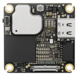
The DJI 04 Air Transmission system is a state-of-the-art wireless communication module designed specifically for drones. It enables high-definition video transmission and low-latency control signals, ensuring seamless communication between the drone and its controller. With its robust design and advanced technology, the DJI 04 Air Transmission system is ideal for professional aerial photography, videography, and industrial drone applications.
Explore Projects Built with dji 04 air transmission
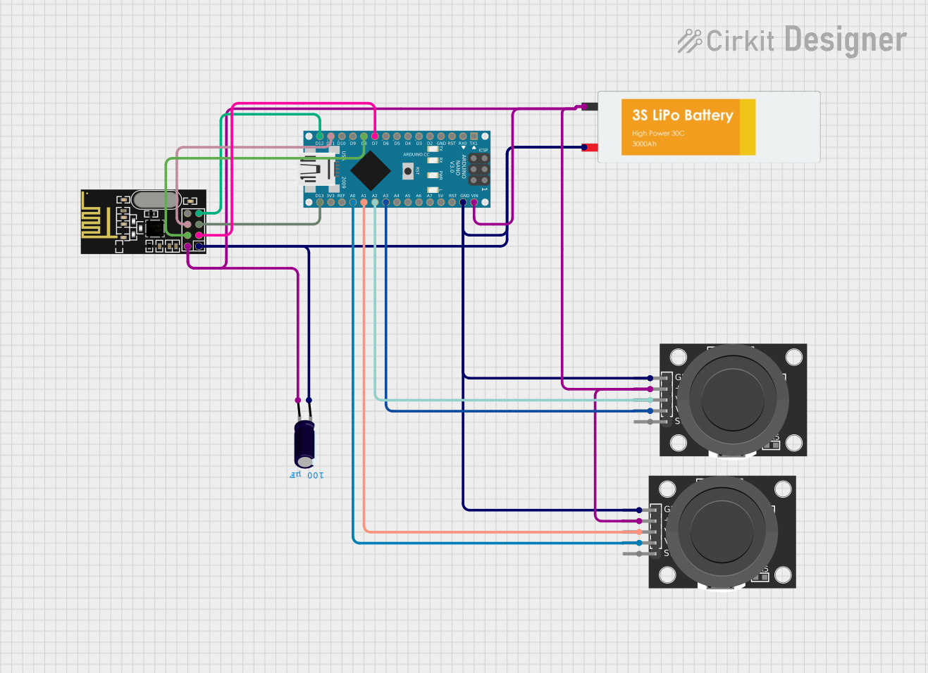

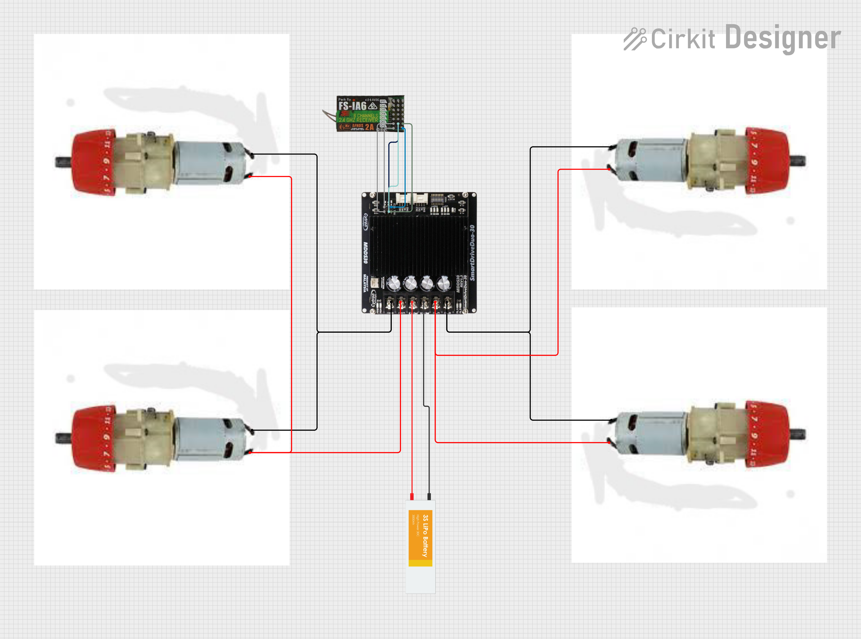
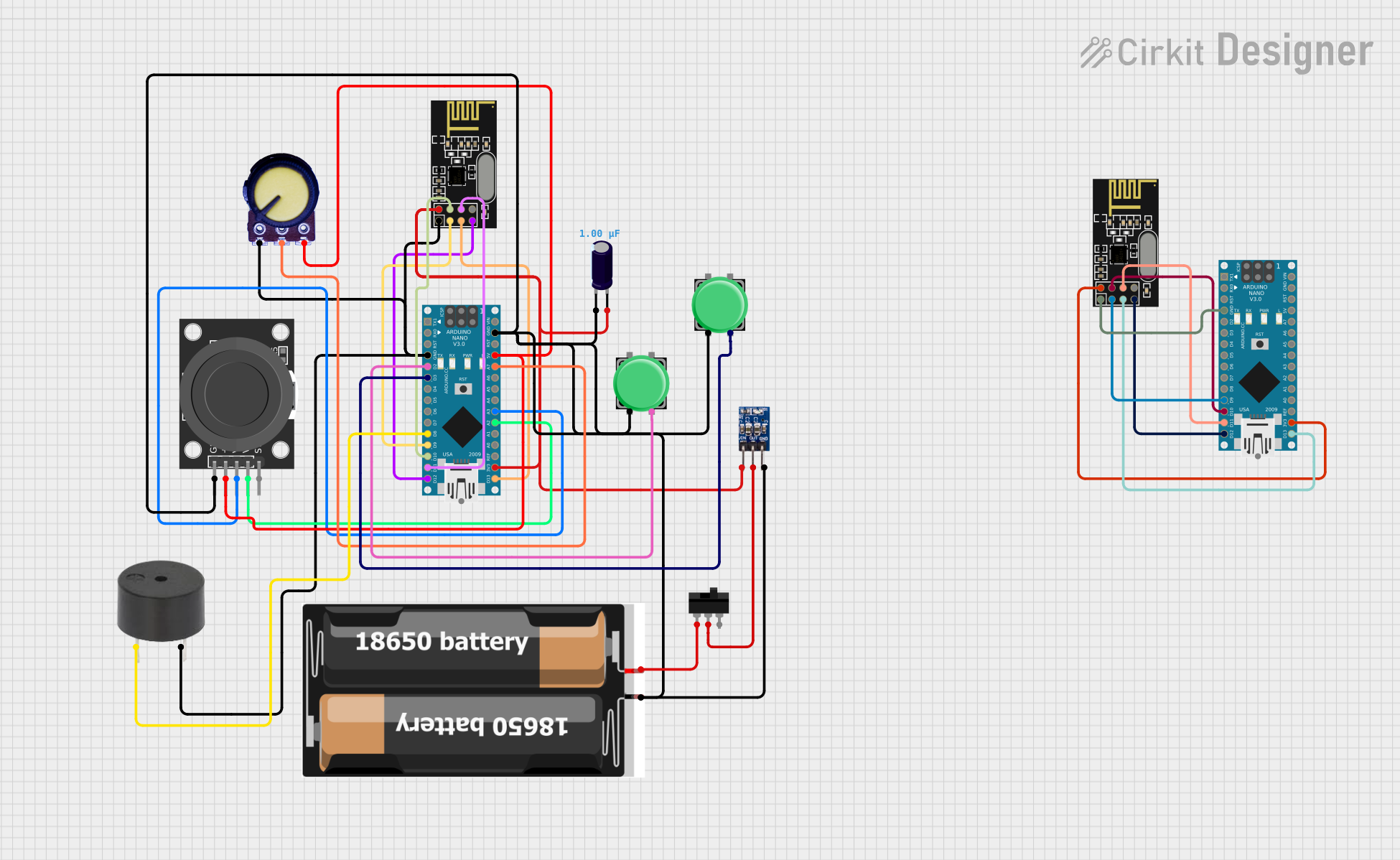
Explore Projects Built with dji 04 air transmission
Common Applications and Use Cases
- High-definition video streaming for drones
- Low-latency control signal transmission
- Professional aerial photography and videography
- Industrial drone operations, such as surveying and mapping
- Search and rescue missions requiring real-time video feedback
Technical Specifications
Key Technical Details
| Parameter | Specification |
|---|---|
| Video Resolution | Up to 1080p at 60fps |
| Latency | As low as 28ms |
| Transmission Range | Up to 10 km (line of sight) |
| Frequency Band | 2.4 GHz / 5.8 GHz (dual-band) |
| Power Supply Voltage | 7.4V to 26.4V |
| Power Consumption | ≤ 8W |
| Operating Temperature | -10°C to 40°C |
| Weight | 50g |
Pin Configuration and Descriptions
| Pin Number | Pin Name | Description |
|---|---|---|
| 1 | GND | Ground connection |
| 2 | VCC | Power supply input (7.4V to 26.4V) |
| 3 | TX | Transmit data (video/control signals) |
| 4 | RX | Receive data (control signals) |
| 5 | UART_TX | UART transmit for debugging or configuration |
| 6 | UART_RX | UART receive for debugging or configuration |
| 7 | ANT1 | Antenna 1 connection for signal transmission |
| 8 | ANT2 | Antenna 2 connection for signal reception |
Usage Instructions
How to Use the Component in a Circuit
- Power Supply: Connect the VCC pin to a stable power source within the range of 7.4V to 26.4V. Ensure the GND pin is connected to the ground of the power source.
- Antenna Setup: Attach compatible antennas to the ANT1 and ANT2 pins for optimal signal transmission and reception.
- Data Connections: Use the TX and RX pins to connect the module to the drone's flight controller for video and control signal transmission.
- UART Interface: For debugging or configuration, connect the UART_TX and UART_RX pins to a compatible UART interface.
- Mounting: Securely mount the module on the drone, ensuring proper airflow for heat dissipation.
Important Considerations and Best Practices
- Line of Sight: For maximum transmission range, maintain a clear line of sight between the drone and the controller.
- Frequency Selection: Choose the appropriate frequency band (2.4 GHz or 5.8 GHz) based on local regulations and environmental interference.
- Heat Management: Avoid enclosing the module in a confined space to prevent overheating.
- Firmware Updates: Regularly check for firmware updates from DJI to ensure optimal performance and compatibility.
- Antenna Placement: Position the antennas to minimize interference and maximize signal strength.
Example Code for Arduino UNO Integration
While the DJI 04 Air Transmission system is not directly designed for Arduino, it can be interfaced for basic control or debugging purposes using the UART interface. Below is an example code snippet for sending data to the module:
#include <SoftwareSerial.h>

// Define RX and TX pins for SoftwareSerial
#define RX_PIN 10
#define TX_PIN 11

// Initialize SoftwareSerial for UART communication
SoftwareSerial djiSerial(RX_PIN, TX_PIN);

void setup() {
  // Start the serial communication with the DJI module
  djiSerial.begin(9600); // Adjust baud rate as per module's specification
  Serial.begin(9600);    // For debugging via Serial Monitor

  Serial.println("DJI 04 Air Transmission - UART Communication Initialized");
}

void loop() {
  // Example: Sending a test command to the DJI module
  String command = "TEST_COMMAND";
  djiSerial.println(command); // Send command to the module

  // Check for response from the module
  if (djiSerial.available()) {
    String response = djiSerial.readString();
    Serial.println("Response from DJI Module: " + response);
  }

  delay(1000); // Wait for 1 second before sending the next command
}
Troubleshooting and FAQs
Common Issues and Solutions
No Video Signal
- Cause: Incorrect antenna placement or damaged antennas.
- Solution: Verify antenna connections and ensure proper placement. Replace damaged antennas if necessary.
High Latency
- Cause: Environmental interference or outdated firmware.
- Solution: Switch to a less congested frequency band and update the firmware.
Module Overheating
- Cause: Poor ventilation or excessive power supply voltage.
- Solution: Ensure proper airflow around the module and verify the power supply voltage is within the specified range.
UART Communication Failure
- Cause: Incorrect baud rate or wiring.
- Solution: Double-check the baud rate and wiring connections. Ensure the RX and TX pins are correctly connected.
Frequently Asked Questions
Can the DJI 04 Air Transmission system be used with non-DJI drones?
- Yes, it can be integrated with non-DJI drones, provided the flight controller supports the required interfaces.
What is the maximum supported video resolution?
- The system supports up to 1080p resolution at 60fps.
Is the module waterproof?
- No, the module is not waterproof. Avoid exposing it to water or excessive moisture.
Can I use multiple modules simultaneously?
- Yes, but ensure proper frequency management to avoid interference between modules.
By following this documentation, users can effectively integrate and operate the DJI 04 Air Transmission system for their drone applications.