Cirkit Designer Logo
Cirkit Designer
Your all-in-one circuit design IDE
Home / 
Component Documentation

How to Use Adafruit PCF8523 RTC: Examples, Pinouts, and Specs

Image of Adafruit PCF8523 RTC
Cirkit Designer LogoDesign with Adafruit PCF8523 RTC in Cirkit Designer

Introduction

The Adafruit PCF8523 RTC is a Real Time Clock (RTC) module that offers precise timekeeping capabilities. It is designed to maintain accurate time with the help of a built-in crystal oscillator and can continue to keep time with a backup battery even when the main power supply is disconnected. This component is ideal for a variety of applications, including data loggers, alarm systems, and other time-sensitive projects.

Common applications and use cases:

  • Clocks and watches
  • Data logging with time stamps
  • Time-based automation (e.g., turning lights on/off)
  • Scheduling events in embedded systems

Explore Projects Built with Adafruit PCF8523 RTC

Use Cirkit Designer to design, explore, and prototype these projects online. Some projects support real-time simulation. Click "Open Project" to start designing instantly!
Arduino UNO-Based Real-Time Clock with I2C LCD Display and IO Expansion
Image of teste: A project utilizing Adafruit PCF8523 RTC in a practical application
This circuit is an Arduino-based real-time clock and display system. It uses an Arduino UNO to interface with a DS1307 RTC module for timekeeping and a 20x4 I2C LCD to display the current time and date. Additionally, a PCF8574 IO Expansion Board is used to extend the I2C bus for additional I/O operations.
Cirkit Designer LogoOpen Project in Cirkit Designer
Dual RTC DS3231 Synchronization with Glyph C3 Microcontroller
Image of DS: A project utilizing Adafruit PCF8523 RTC in a practical application
This circuit integrates two RTC DS3231 real-time clock modules with a Glyph C3 microcontroller. The RTC modules are connected to the microcontroller via I2C communication protocol, using the SCL and SDA lines for clock and data respectively. Both RTC modules and the microcontroller share a common power supply (3V3) and ground (GND), indicating that they operate at the same voltage level.
Cirkit Designer LogoOpen Project in Cirkit Designer
Arduino UNO with DS1307 RTC Controlled LED Lighting System
Image of li8: A project utilizing Adafruit PCF8523 RTC in a practical application
This circuit features an Arduino UNO connected to a DS1307 Real Time Clock (RTC) module for timekeeping and a red LED with a series resistor for indication purposes. The Arduino communicates with the RTC via I2C (using A4 and A5 pins for SDA and SCL, respectively), and controls the LED connected to digital pin D8 through a 330-ohm resistor. The embedded code sets the RTC time, checks the current time, and turns the LED on or off based on the specified time condition (between 11:00 AM and 11:43 AM).
Cirkit Designer LogoOpen Project in Cirkit Designer
Glyph C3 Microcontroller with DS3231 RTC Timekeeping Circuit
Image of Glyph-C3-DS3231-I2C-Real-Time Clock Module: A project utilizing Adafruit PCF8523 RTC in a practical application
This circuit connects a Glyph C3 microcontroller to a DS3231 Real Time Clock (RTC) module. The microcontroller provides 3.3V power and ground to the RTC, and they communicate via the I2C protocol, using the SDA and SCL lines. This setup allows the microcontroller to keep track of real-time, even when it is powered off or reset.
Cirkit Designer LogoOpen Project in Cirkit Designer

Explore Projects Built with Adafruit PCF8523 RTC

Use Cirkit Designer to design, explore, and prototype these projects online. Some projects support real-time simulation. Click "Open Project" to start designing instantly!
Image of teste: A project utilizing Adafruit PCF8523 RTC in a practical application
Arduino UNO-Based Real-Time Clock with I2C LCD Display and IO Expansion
This circuit is an Arduino-based real-time clock and display system. It uses an Arduino UNO to interface with a DS1307 RTC module for timekeeping and a 20x4 I2C LCD to display the current time and date. Additionally, a PCF8574 IO Expansion Board is used to extend the I2C bus for additional I/O operations.
Cirkit Designer LogoOpen Project in Cirkit Designer
Image of DS: A project utilizing Adafruit PCF8523 RTC in a practical application
Dual RTC DS3231 Synchronization with Glyph C3 Microcontroller
This circuit integrates two RTC DS3231 real-time clock modules with a Glyph C3 microcontroller. The RTC modules are connected to the microcontroller via I2C communication protocol, using the SCL and SDA lines for clock and data respectively. Both RTC modules and the microcontroller share a common power supply (3V3) and ground (GND), indicating that they operate at the same voltage level.
Cirkit Designer LogoOpen Project in Cirkit Designer
Image of li8: A project utilizing Adafruit PCF8523 RTC in a practical application
Arduino UNO with DS1307 RTC Controlled LED Lighting System
This circuit features an Arduino UNO connected to a DS1307 Real Time Clock (RTC) module for timekeeping and a red LED with a series resistor for indication purposes. The Arduino communicates with the RTC via I2C (using A4 and A5 pins for SDA and SCL, respectively), and controls the LED connected to digital pin D8 through a 330-ohm resistor. The embedded code sets the RTC time, checks the current time, and turns the LED on or off based on the specified time condition (between 11:00 AM and 11:43 AM).
Cirkit Designer LogoOpen Project in Cirkit Designer
Image of Glyph-C3-DS3231-I2C-Real-Time Clock Module: A project utilizing Adafruit PCF8523 RTC in a practical application
Glyph C3 Microcontroller with DS3231 RTC Timekeeping Circuit
This circuit connects a Glyph C3 microcontroller to a DS3231 Real Time Clock (RTC) module. The microcontroller provides 3.3V power and ground to the RTC, and they communicate via the I2C protocol, using the SDA and SCL lines. This setup allows the microcontroller to keep track of real-time, even when it is powered off or reset.
Cirkit Designer LogoOpen Project in Cirkit Designer

Technical Specifications

Key Technical Details

  • Voltage Supply: 1.8V to 5.5V
  • Current Consumption: 55 μA (typical)
  • Time Accuracy: ±2ppm from 0°C to +40°C
  • Battery Backup: Yes (CR1220 coin cell)
  • Interface: I2C
  • I2C Address: 0x68 (7-bit)

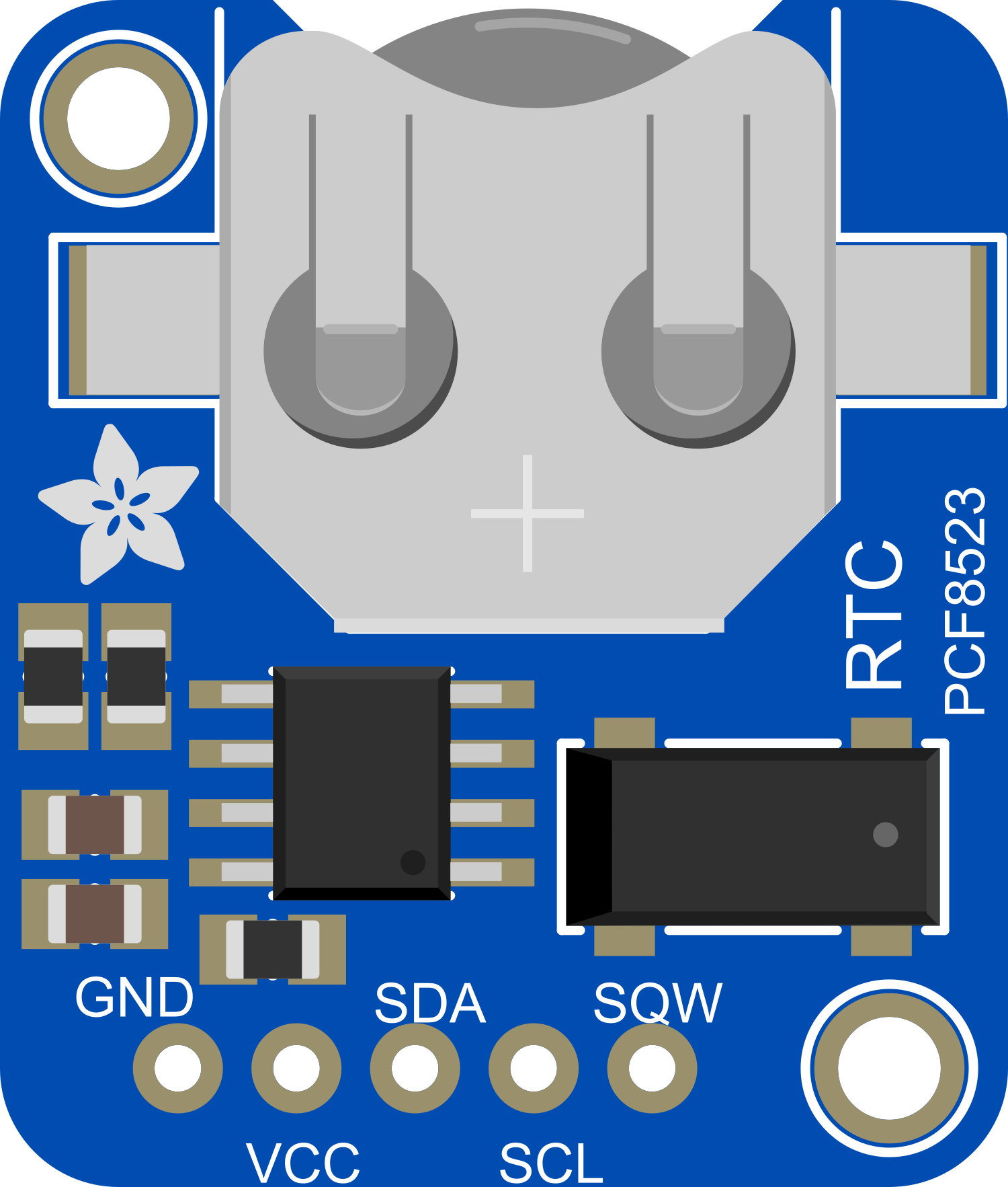
Pin Configuration and Descriptions

Pin Number Name Description
1 VCC Power supply (1.8V to 5.5V)
2 GND Ground connection
3 SDA I2C Data Line
4 SCL I2C Clock Line
5 INT Interrupt output (active low)
6 CLKOUT Clock output for peripheral devices

Usage Instructions

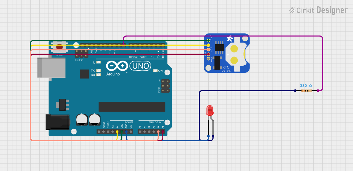
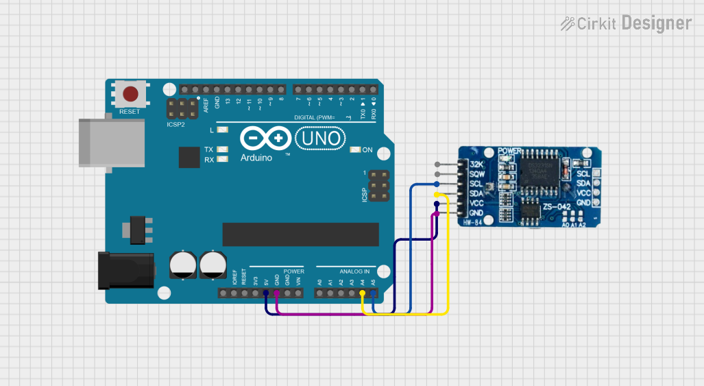
How to Use the Component in a Circuit

  1. Power Connections: Connect the VCC pin to a 1.8V to 5.5V power supply and the GND pin to the ground.
  2. I2C Connections: Connect the SDA and SCL pins to the I2C data and clock lines, respectively.
  3. Backup Battery: Insert a CR1220 coin cell into the battery holder to enable timekeeping during power loss.
  4. Arduino Connection: For use with an Arduino UNO, connect SDA to A4, SCL to A5, VCC to 5V, and GND to ground.

Important Considerations and Best Practices

  • Ensure that the power supply voltage is within the specified range to avoid damaging the RTC.
  • The I2C bus requires pull-up resistors; most Arduino boards have these built-in, but if you're using a different microcontroller, you may need to add them.
  • When placing the backup battery, ensure the correct polarity to prevent damage to the RTC.
  • For accurate timekeeping, avoid placing the RTC module near heat sources or components that generate significant heat.

Example Code for Arduino UNO

#include <Wire.h>
#include "RTClib.h"

RTC_PCF8523 rtc;

void setup() {
  Wire.begin();
  Serial.begin(9600);

  // Check if the RTC is connected correctly
  if (!rtc.begin()) {
    Serial.println("Couldn't find RTC");
    while (1);
  }

  // Check if the RTC has lost power and if so, set the time
  if (!rtc.initialized() || rtc.lostPower()) {
    Serial.println("RTC is NOT initialized, let's set the time!");
    // This line sets the RTC to the date & time this sketch was compiled
    rtc.adjust(DateTime(F(__DATE__), F(__TIME__)));
  }
}

void loop() {
  DateTime now = rtc.now();

  // Print the current date and time
  Serial.print(now.year(), DEC);
  Serial.print('/');
  Serial.print(now.month(), DEC);
  Serial.print('/');
  Serial.print(now.day(), DEC);
  Serial.print(" ");
  Serial.print(now.hour(), DEC);
  Serial.print(':');
  Serial.print(now.minute(), DEC);
  Serial.print(':');
  Serial.print(now.second(), DEC);
  Serial.println();

  // Wait for a second
  delay(1000);
}

Troubleshooting and FAQs

Common Issues

  • Time not accurate: Ensure the backup battery is installed correctly and has charge.
  • I2C communication failure: Check the wiring, ensure pull-up resistors are in place, and verify that no other device on the I2C bus has the same address.
  • No response from the RTC: Make sure the RTC module is properly powered and that the correct I2C address is being used in the code.

Solutions and Tips for Troubleshooting

  • If the time is not accurate, replace the backup battery with a new one.
  • Use an I2C scanner sketch to check if the RTC is detected on the I2C bus.
  • Ensure that the Arduino libraries for the RTC are correctly installed and included in your sketch.

FAQs

Q: Can the PCF8523 RTC module be used with a 3.3V system? A: Yes, the module can operate from 1.8V to 5.5V, making it suitable for both 3.3V and 5V systems.

Q: How long will the backup battery last? A: The battery life depends on the quality of the battery and the environmental conditions but typically lasts for a few years.

Q: Is it necessary to use an external crystal with the PCF8523 RTC? A: No, the PCF8523 has an integrated crystal oscillator that provides accurate timekeeping.