How to Use STEP DOWN : Examples, Pinouts, and Specs
Introduction
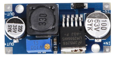
The STEP DOWN converter, manufactured by DEWA with part ID audi variasi, is a DC-DC buck converter designed to reduce voltage from a higher level to a lower level while simultaneously increasing current. This component is widely used in power management systems to efficiently step down voltage for various electronic devices and circuits.
Explore Projects Built with STEP DOWN


Explore Projects Built with STEP DOWN
Common Applications and Use Cases
- Powering low-voltage devices from a higher-voltage source (e.g., 12V to 5V conversion)
- Battery-powered systems to regulate voltage levels
- Embedded systems and microcontroller-based projects
- LED drivers and portable electronics
- Renewable energy systems, such as solar power setups
Technical Specifications
The following table outlines the key technical details of the STEP DOWN converter:
| Parameter | Value |
|---|---|
| Input Voltage Range | 6V to 40V |
| Output Voltage Range | 1.25V to 35V (adjustable) |
| Maximum Output Current | 3A (with proper heat dissipation) |
| Efficiency | Up to 92% |
| Switching Frequency | 150 kHz |
| Operating Temperature | -40°C to +85°C |
| Dimensions | 43mm x 21mm x 14mm |
Pin Configuration and Descriptions
The STEP DOWN converter typically has the following pin configuration:
| Pin Name | Description |
|---|---|
| VIN | Input voltage pin. Connect the higher voltage source here (e.g., 12V or 24V). |
| GND | Ground pin. Connect to the ground of the power source and the load. |
| VOUT | Output voltage pin. Provides the stepped-down voltage to the load. |
| ADJ | Adjustment pin. Used to set the output voltage via an external potentiometer. |
Usage Instructions
How to Use the Component in a Circuit
Connect the Input Voltage (VIN):
- Attach the positive terminal of the power source to the VIN pin.
- Connect the negative terminal of the power source to the GND pin.
Set the Output Voltage:
- Use the ADJ pin to adjust the output voltage. Typically, this is done by turning a potentiometer connected to the ADJ pin.
- Measure the output voltage at the VOUT pin using a multimeter to ensure it matches your desired level.
Connect the Load:
- Attach the positive terminal of your load to the VOUT pin.
- Connect the negative terminal of your load to the GND pin.
Verify Connections:
- Double-check all connections to ensure proper polarity and secure wiring.
Power On:
- Turn on the power source and monitor the output voltage to confirm proper operation.
Important Considerations and Best Practices
- Heat Dissipation: Ensure adequate heat sinking or airflow if the converter operates near its maximum current rating (3A).
- Input Voltage Range: Do not exceed the specified input voltage range (6V to 40V) to avoid damaging the component.
- Output Voltage Adjustment: Use a precision screwdriver to adjust the potentiometer for fine-tuning the output voltage.
- Capacitor Placement: Place input and output capacitors close to the converter to minimize noise and improve stability.
- Arduino Compatibility: The STEP DOWN converter can be used to power Arduino boards by stepping down a higher voltage (e.g., 12V) to 5V.
Example: Using the STEP DOWN Converter with an Arduino UNO
Here is an example of how to use the STEP DOWN converter to power an Arduino UNO:
- Set the output voltage of the STEP DOWN converter to 5V.
- Connect the VOUT pin of the converter to the 5V pin of the Arduino UNO.
- Connect the GND pin of the converter to the GND pin of the Arduino UNO.
// Example Arduino code to blink an LED
// Ensure the Arduino is powered via the STEP DOWN converter (set to 5V).

const int ledPin = 13; // Pin connected to the onboard LED

void setup() {
  pinMode(ledPin, OUTPUT); // Set the LED pin as an output
}

void loop() {
  digitalWrite(ledPin, HIGH); // Turn the LED on
  delay(1000);                // Wait for 1 second
  digitalWrite(ledPin, LOW);  // Turn the LED off
  delay(1000);                // Wait for 1 second
}
Troubleshooting and FAQs
Common Issues and Solutions
No Output Voltage:
- Cause: Incorrect wiring or loose connections.
- Solution: Verify all connections, ensuring proper polarity and secure wiring.
Output Voltage is Incorrect:
- Cause: Potentiometer not adjusted correctly.
- Solution: Use a multimeter to measure the output voltage and adjust the potentiometer.
Overheating:
- Cause: Excessive current draw or insufficient heat dissipation.
- Solution: Add a heatsink or improve airflow around the converter.
Noise or Instability:
- Cause: Missing or improperly placed capacitors.
- Solution: Add input and output capacitors close to the converter pins.
FAQs
Q1: Can the STEP DOWN converter handle AC input?
A1: No, the STEP DOWN converter is designed for DC input only. Use a rectifier circuit to convert AC to DC before connecting.
Q2: How do I calculate the required input voltage?
A2: Ensure the input voltage is at least 1.5V higher than the desired output voltage for proper operation.
Q3: Can I use the STEP DOWN converter to charge batteries?
A3: Yes, but ensure the output voltage and current are within the battery's charging specifications.
Q4: What happens if I exceed the maximum input voltage?
A4: Exceeding the input voltage range (40V) can permanently damage the converter. Always stay within the specified range.