Cirkit Designer Logo
Cirkit Designer
Your all-in-one circuit design IDE
Home / 
Component Documentation

How to Use Adafruit MacroPad RP2040: Examples, Pinouts, and Specs

Image of Adafruit MacroPad RP2040
Cirkit Designer LogoDesign with Adafruit MacroPad RP2040 in Cirkit Designer

Introduction

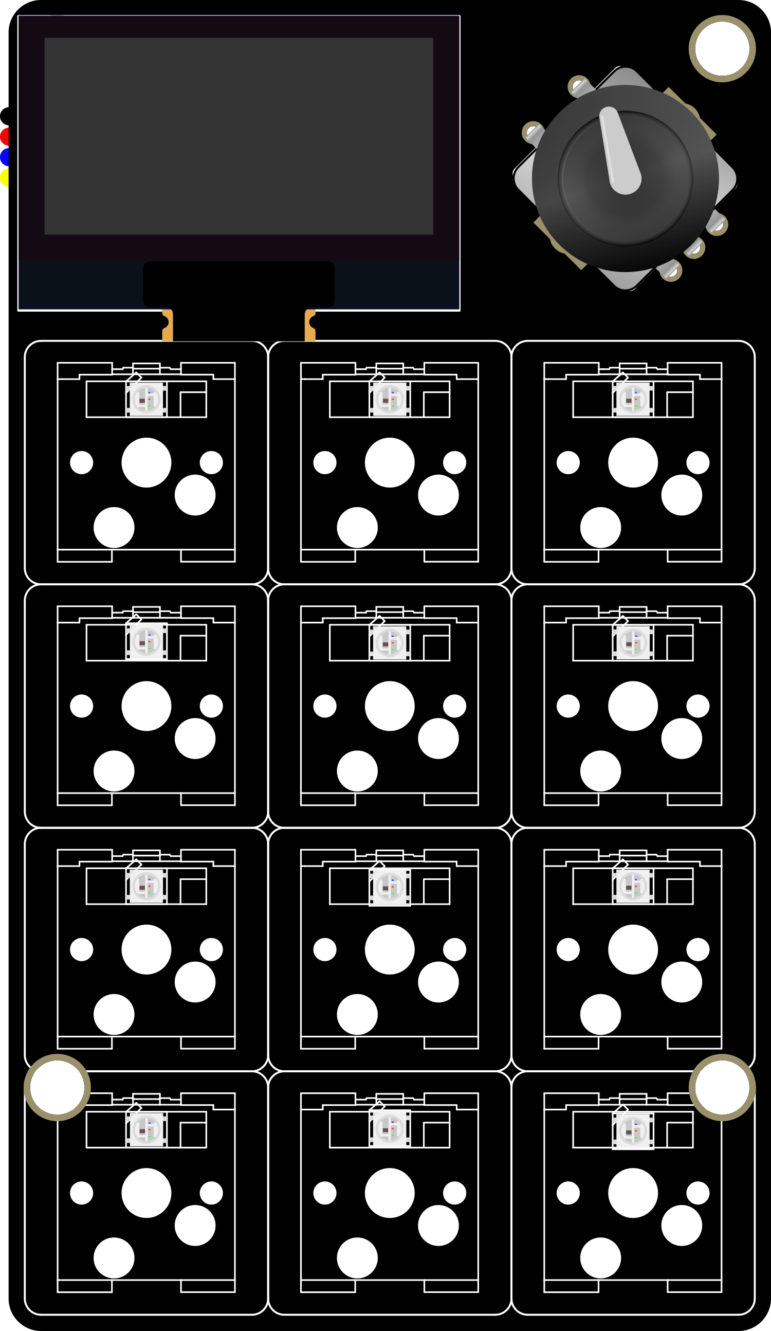
The Adafruit MacroPad RP2040 is a versatile and compact mechanical keypad featuring the powerful Raspberry Pi RP2040 microcontroller. With programmable keys and individual RGB backlighting, it is an ideal tool for creating custom macro keyboards, game controllers, and various automation interfaces. Its ease of use and flexibility make it suitable for hobbyists, gamers, and professionals looking to streamline their workflows.

Explore Projects Built with Adafruit MacroPad RP2040

Use Cirkit Designer to design, explore, and prototype these projects online. Some projects support real-time simulation. Click "Open Project" to start designing instantly!
Adafruit QT Py RP2040 Development Board for Custom Projects
Image of perfboard: A project utilizing Adafruit MacroPad RP2040 in a practical application
The circuit consists of a single Adafruit QT Py RP2040 microcontroller with no external connections or additional components. It appears to be a standalone setup, possibly for initial testing or programming purposes.
Cirkit Designer LogoOpen Project in Cirkit Designer
Battery-Powered Smart Sensor Hub with Adafruit QT Py RP2040
Image of wearable final: A project utilizing Adafruit MacroPad RP2040 in a practical application
This circuit features an Adafruit QT Py RP2040 microcontroller interfaced with an APDS9960 proximity sensor, an MPU6050 accelerometer and gyroscope, and an OLED display via I2C communication. It also includes a buzzer controlled by the microcontroller and is powered by a 3.7V LiPo battery with a toggle switch for power control.
Cirkit Designer LogoOpen Project in Cirkit Designer
Battery-Powered Smart Light with Proximity Sensor and OLED Display using Adafruit QT Py RP2040
Image of lab: A project utilizing Adafruit MacroPad RP2040 in a practical application
This circuit is a portable, battery-powered system featuring an Adafruit QT Py RP2040 microcontroller that interfaces with an OLED display, a proximity sensor, an accelerometer, and an RGB LED strip. The system is powered by a lithium-ion battery with a step-up boost converter to provide 5V for the LED strip, and it includes a toggle switch for power control. The microcontroller communicates with the sensors and display via I2C.
Cirkit Designer LogoOpen Project in Cirkit Designer
Battery-Powered Sensor Hub with Adafruit QT Py RP2040 and OLED Display
Image of 512: A project utilizing Adafruit MacroPad RP2040 in a practical application
This circuit features an Adafruit QT Py RP2040 microcontroller interfacing with an MPU-6050 accelerometer, an Adafruit APDS-9960 sensor, and a 0.96" OLED display via I2C communication. It is powered by a 3.7V LiPo battery and includes a green LED with a current-limiting resistor connected to an analog pin of the microcontroller.
Cirkit Designer LogoOpen Project in Cirkit Designer

Explore Projects Built with Adafruit MacroPad RP2040

Use Cirkit Designer to design, explore, and prototype these projects online. Some projects support real-time simulation. Click "Open Project" to start designing instantly!
Image of perfboard: A project utilizing Adafruit MacroPad RP2040 in a practical application
Adafruit QT Py RP2040 Development Board for Custom Projects
The circuit consists of a single Adafruit QT Py RP2040 microcontroller with no external connections or additional components. It appears to be a standalone setup, possibly for initial testing or programming purposes.
Cirkit Designer LogoOpen Project in Cirkit Designer
Image of wearable final: A project utilizing Adafruit MacroPad RP2040 in a practical application
Battery-Powered Smart Sensor Hub with Adafruit QT Py RP2040
This circuit features an Adafruit QT Py RP2040 microcontroller interfaced with an APDS9960 proximity sensor, an MPU6050 accelerometer and gyroscope, and an OLED display via I2C communication. It also includes a buzzer controlled by the microcontroller and is powered by a 3.7V LiPo battery with a toggle switch for power control.
Cirkit Designer LogoOpen Project in Cirkit Designer
Image of lab: A project utilizing Adafruit MacroPad RP2040 in a practical application
Battery-Powered Smart Light with Proximity Sensor and OLED Display using Adafruit QT Py RP2040
This circuit is a portable, battery-powered system featuring an Adafruit QT Py RP2040 microcontroller that interfaces with an OLED display, a proximity sensor, an accelerometer, and an RGB LED strip. The system is powered by a lithium-ion battery with a step-up boost converter to provide 5V for the LED strip, and it includes a toggle switch for power control. The microcontroller communicates with the sensors and display via I2C.
Cirkit Designer LogoOpen Project in Cirkit Designer
Image of 512: A project utilizing Adafruit MacroPad RP2040 in a practical application
Battery-Powered Sensor Hub with Adafruit QT Py RP2040 and OLED Display
This circuit features an Adafruit QT Py RP2040 microcontroller interfacing with an MPU-6050 accelerometer, an Adafruit APDS-9960 sensor, and a 0.96" OLED display via I2C communication. It is powered by a 3.7V LiPo battery and includes a green LED with a current-limiting resistor connected to an analog pin of the microcontroller.
Cirkit Designer LogoOpen Project in Cirkit Designer

Common Applications and Use Cases

  • Custom macro keyboards for productivity
  • DIY game controllers
  • Stream decks for content creators
  • Home automation control panels
  • Educational tools for learning programming and electronics

Technical Specifications

Key Technical Details

  • Microcontroller: Raspberry Pi RP2040
  • Input Voltage (VIN): 5V via USB-C
  • Logic Voltage: 3.3V
  • Onboard Peripherals:
    • 12 x Cherry MX-compatible key switches
    • 12 x RGB NeoPixel LEDs
    • 1 x Rotary encoder with push switch
    • 1 x 128x64 OLED display
    • 1 x Piezo buzzer
    • 1 x STEMMA QT connector for I2C

Pin Configuration and Descriptions

Pin Number Function Description
1 GND Ground
2 VBUS USB input voltage (5V)
3 3V3 3.3V output from the onboard voltage regulator
4-15 GPIO 0 - GPIO 11 General Purpose I/O pins for keys and rotary encoder
16 SDA I2C Data line for OLED display and external I2C devices
17 SCL I2C Clock line for OLED display and external I2C devices
18 EN Enable pin for the 3.3V regulator

Usage Instructions

How to Use the Component in a Circuit

  1. Powering the MacroPad: Connect the USB-C cable to the MacroPad and a 5V USB power source.
  2. Connecting Key Switches: Insert Cherry MX-compatible key switches into the provided slots.
  3. Programming: Use the Arduino IDE or CircuitPython to program the RP2040 microcontroller.
  4. Customization: Assign macros or functions to keys using the provided libraries and examples.

Important Considerations and Best Practices

  • Ensure the power source does not exceed the recommended voltage.
  • When soldering components, maintain a clean environment and use proper safety equipment.
  • Use ESD precautions when handling the MacroPad to prevent damage to sensitive components.
  • Customize the key functions and RGB lighting to suit your specific needs and preferences.

Troubleshooting and FAQs

Common Issues

  • MacroPad not recognized by computer: Check the USB cable and connections. Try a different USB port or cable.
  • Keys not responding: Verify that the key switches are properly seated and soldered if necessary.
  • OLED display not working: Ensure that the OLED is correctly connected and check for solder bridges.

Solutions and Tips for Troubleshooting

  • Resetting the MacroPad: Locate the reset button on the back of the PCB and press it to reset the device.
  • Firmware Update: Periodically check for firmware updates that may resolve existing issues.
  • Community Support: Adafruit provides a forum for users to discuss issues and solutions.

FAQs

  • Q: Can I use any key switches with the MacroPad?
    • A: The MacroPad is compatible with any Cherry MX-compatible key switches.
  • Q: How do I change the RGB lighting?
    • A: RGB lighting can be controlled via software using the provided libraries and examples.

Example Code for Arduino UNO

Below is an example code snippet for initializing the MacroPad and setting up a simple key press event. This code is intended for use with the Arduino IDE.

#include <Adafruit_Keypad.h>
#include <Adafruit_NeoPixel.h>

// Define the number of keys and LEDs
#define NUM_KEYS 12
#define NUM_LEDS 12

// Create the keypad and LED objects
Adafruit_Keypad keypad = Adafruit_Keypad(makeKeymap(keys), 4, 3, ROWS, COLS);
Adafruit_NeoPixel strip = Adafruit_NeoPixel(NUM_LEDS, PIN, NEO_GRB + NEO_KHZ800);

void setup() {
  // Initialize the keypad and LEDs
  keypad.begin();
  strip.begin();
  strip.show(); // Initialize all pixels to 'off'
}

void loop() {
  // Put your main code here, to run repeatedly:
  keypad.tick();

  while (keypad.available()) {
    keypadEvent e = keypad.read();
    // Handle the key press event
    if (e.bit.EVENT == KEY_JUST_PRESSED) {
      // Example: Light up the corresponding LED when a key is pressed
      strip.setPixelColor(e.bit.KEY, strip.Color(100, 0, 0)); // Red color
      strip.show();
    }
    else if (e.bit.EVENT == KEY_JUST_RELEASED) {
      // Turn off the LED when the key is released
      strip.setPixelColor(e.bit.KEY, strip.Color(0, 0, 0)); // Off
      strip.show();
    }
  }
}

Remember to replace makeKeymap(keys), ROWS, COLS, and PIN with the appropriate values for your setup. This code is a basic starting point and can be expanded to include more complex functionality such as handling multiple key presses, custom macros, and dynamic lighting effects.