Cirkit Designer Logo
Cirkit Designer
Your all-in-one circuit design IDE
Home / 
Component Documentation

How to Use Camdenboss CTB0158-4: Examples, Pinouts, and Specs


Image of Camdenboss CTB0158-4
Cirkit Designer LogoDesign with Camdenboss CTB0158-4 in Cirkit Designer

Introduction

The CamdenBoss CTB0158/4 is a compact terminal block designed for efficient wiring and secure electrical connections. It features four terminals, making it ideal for organizing and managing multiple electrical connections in a compact form factor. This component is widely used in industrial, commercial, and DIY electronics projects where reliable and organized wiring is essential.

Explore Projects Built with Camdenboss CTB0158-4
Use Cirkit Designer to design, explore, and prototype these projects online. Some projects support real-time simulation. Click "Open Project" to start designing instantly!
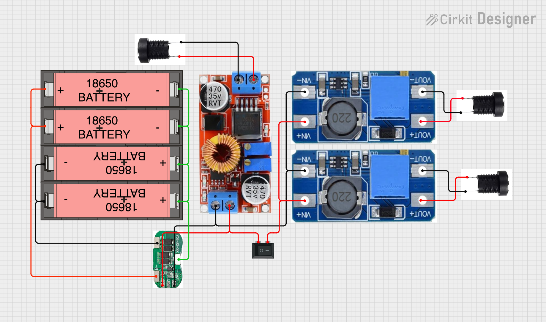
Battery-Powered Adjustable Voltage Regulator with Li-ion 18650 Batteries and BMS
Image of mini ups: A project utilizing Camdenboss CTB0158-4 in a practical application
This circuit is a power management system that uses four Li-ion 18650 batteries connected to a 2S 30A BMS for battery management and protection. The system includes step-up and step-down voltage regulators to provide adjustable output voltages, controlled by a rocker switch, and multiple DC jacks for power input and output.
Cirkit Designer LogoOpen Project in Cirkit Designer
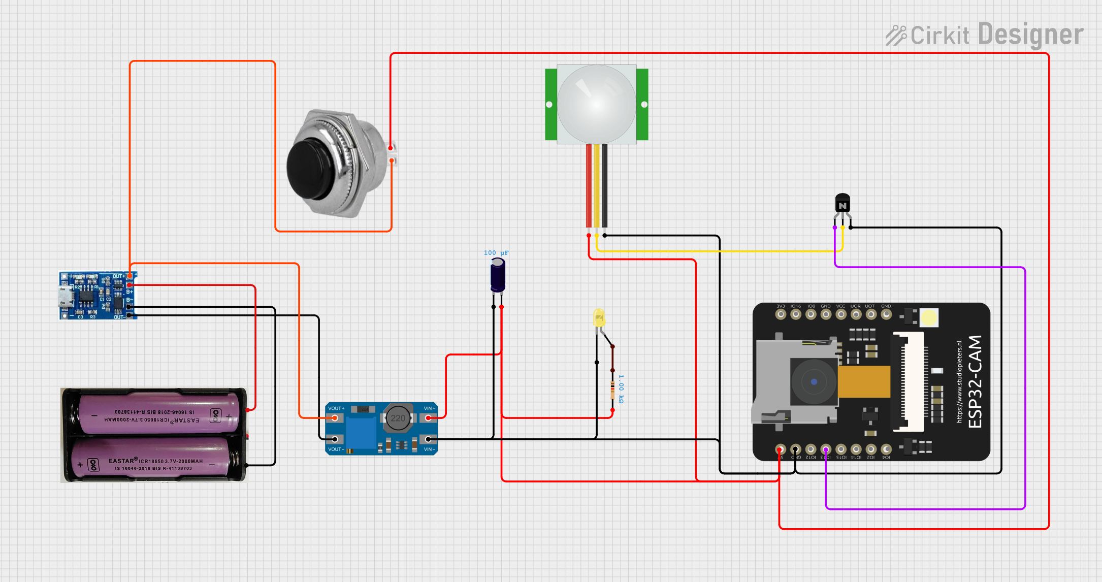
ESP32 CAM PIR Sensor Security Camera with Battery Management
Image of intruder alert system: A project utilizing Camdenboss CTB0158-4 in a practical application
This is a motion-activated camera system powered by a 7.4V battery with a charging module. It uses a PIR sensor to detect motion and an ESP32 CAM microcontroller to process the signal and activate a yellow LED through an NPN transistor. A voltage booster and capacitor are included for power management, and a momentary switch allows for manual power control.
Cirkit Designer LogoOpen Project in Cirkit Designer
Satellite-Based Timing and Navigation System with SDR and Atomic Clock Synchronization
Image of GPS 시스템 측정 구성도_Confirm: A project utilizing Camdenboss CTB0158-4 in a practical application
This circuit appears to be a complex system involving power supply management, GPS and timing synchronization, and data communication. It includes a SI-TEX G1 Satellite Compass for GPS data, an XHTF1021 Atomic Rubidium Clock for precise timing, and Ettus USRP B200 units for software-defined radio communication. Power is supplied through various SMPS units and distributed via terminal blocks and DC jacks. Data communication is facilitated by Beelink MINI S12 N95 computers, RS232 splitters, and a 1000BASE-T Media Converter for network connectivity. RF Directional Couplers are used to interface antennas with the USRP units, and the entire system is likely contained within cases for protection and organization.
Cirkit Designer LogoOpen Project in Cirkit Designer
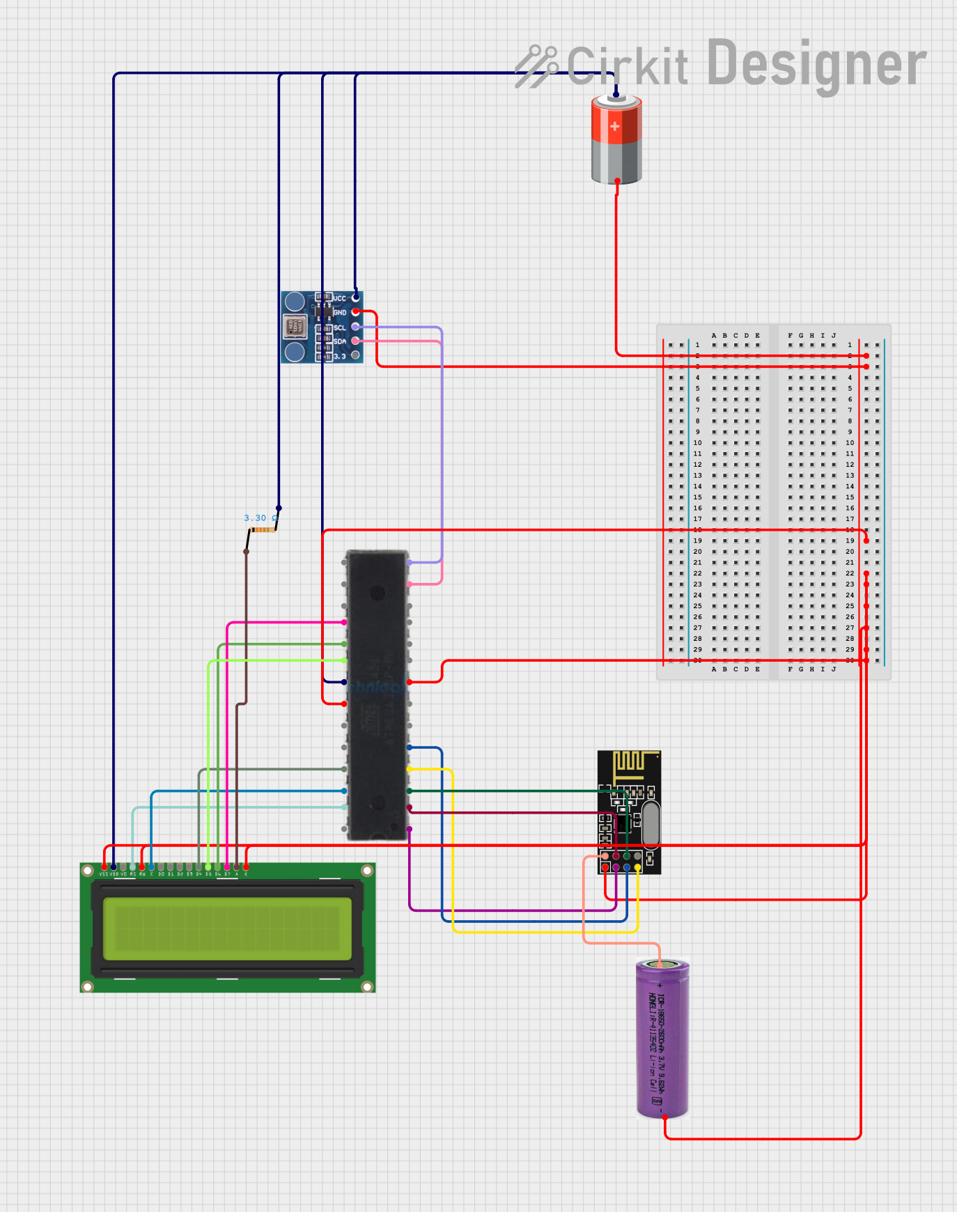
Arduino BMP180 Tire Pressure Monitoring System with LCD Display and NRF24L01 Wireless Transmission
Image of TPMS: A project utilizing Camdenboss CTB0158-4 in a practical application
This circuit is designed for a Tire Pressure Monitoring System using an ATmega328P microcontroller. It reads temperature and pressure data from BMP180 sensors, displays the readings on a 16x2 LCD, and transmits the data wirelessly via an NRF24L01 module. The circuit is powered by a 5V battery, with a 3.3V battery specifically for the NRF24L01, and includes a resistor for the LCD backlight.
Cirkit Designer LogoOpen Project in Cirkit Designer

Explore Projects Built with Camdenboss CTB0158-4

Use Cirkit Designer to design, explore, and prototype these projects online. Some projects support real-time simulation. Click "Open Project" to start designing instantly!
Image of mini ups: A project utilizing Camdenboss CTB0158-4 in a practical application
Battery-Powered Adjustable Voltage Regulator with Li-ion 18650 Batteries and BMS
This circuit is a power management system that uses four Li-ion 18650 batteries connected to a 2S 30A BMS for battery management and protection. The system includes step-up and step-down voltage regulators to provide adjustable output voltages, controlled by a rocker switch, and multiple DC jacks for power input and output.
Cirkit Designer LogoOpen Project in Cirkit Designer
Image of intruder alert system: A project utilizing Camdenboss CTB0158-4 in a practical application
ESP32 CAM PIR Sensor Security Camera with Battery Management
This is a motion-activated camera system powered by a 7.4V battery with a charging module. It uses a PIR sensor to detect motion and an ESP32 CAM microcontroller to process the signal and activate a yellow LED through an NPN transistor. A voltage booster and capacitor are included for power management, and a momentary switch allows for manual power control.
Cirkit Designer LogoOpen Project in Cirkit Designer
Image of GPS 시스템 측정 구성도_Confirm: A project utilizing Camdenboss CTB0158-4 in a practical application
Satellite-Based Timing and Navigation System with SDR and Atomic Clock Synchronization
This circuit appears to be a complex system involving power supply management, GPS and timing synchronization, and data communication. It includes a SI-TEX G1 Satellite Compass for GPS data, an XHTF1021 Atomic Rubidium Clock for precise timing, and Ettus USRP B200 units for software-defined radio communication. Power is supplied through various SMPS units and distributed via terminal blocks and DC jacks. Data communication is facilitated by Beelink MINI S12 N95 computers, RS232 splitters, and a 1000BASE-T Media Converter for network connectivity. RF Directional Couplers are used to interface antennas with the USRP units, and the entire system is likely contained within cases for protection and organization.
Cirkit Designer LogoOpen Project in Cirkit Designer
Image of TPMS: A project utilizing Camdenboss CTB0158-4 in a practical application
Arduino BMP180 Tire Pressure Monitoring System with LCD Display and NRF24L01 Wireless Transmission
This circuit is designed for a Tire Pressure Monitoring System using an ATmega328P microcontroller. It reads temperature and pressure data from BMP180 sensors, displays the readings on a 16x2 LCD, and transmits the data wirelessly via an NRF24L01 module. The circuit is powered by a 5V battery, with a 3.3V battery specifically for the NRF24L01, and includes a resistor for the LCD backlight.
Cirkit Designer LogoOpen Project in Cirkit Designer

Common Applications and Use Cases

  • Industrial control panels and automation systems
  • Power distribution in electrical circuits
  • Prototyping and DIY electronics projects
  • Secure connections in home automation systems
  • Wiring management in enclosures and junction boxes

Technical Specifications

The following table outlines the key technical details of the CamdenBoss CTB0158/4 terminal block:

Parameter Specification
Manufacturer CamdenBoss
Part Number CTB0158/4
Number of Terminals 4
Terminal Pitch 5.08 mm
Rated Voltage 300 V
Rated Current 16 A
Wire Size Range 24–12 AWG
Material (Housing) Polyamide (PA66), UL94-V0 flame retardant
Operating Temperature -40°C to +105°C
Mounting Type PCB (Through-Hole)
Connection Type Screw Terminal

Pin Configuration and Descriptions

The CTB0158/4 terminal block has four screw terminals, each corresponding to a single electrical connection. The pin configuration is as follows:

Pin Number Description
1 Terminal 1 (Input/Output)
2 Terminal 2 (Input/Output)
3 Terminal 3 (Input/Output)
4 Terminal 4 (Input/Output)

Each terminal is designed to securely hold a wire using a screw mechanism, ensuring a reliable electrical connection.

Usage Instructions

How to Use the CTB0158/4 in a Circuit

  1. Prepare the Wires: Strip the insulation from the ends of the wires you intend to connect, exposing approximately 5–7 mm of conductor.
  2. Insert the Wires: Loosen the screws on the terminal block using a screwdriver. Insert the stripped wire ends into the corresponding terminal slots.
  3. Secure the Connection: Tighten the screws to clamp the wires securely in place. Ensure there is no exposed conductor outside the terminal block to avoid short circuits.
  4. Mount the Terminal Block: If using on a PCB, solder the through-hole pins of the terminal block to the PCB pads. Ensure proper alignment and secure solder joints.

Important Considerations and Best Practices

  • Wire Size Compatibility: Ensure the wires used are within the supported range (24–12 AWG) for optimal connection.
  • Tightening Torque: Do not overtighten the screws, as this may damage the terminal block or the wires.
  • Avoid Overloading: Do not exceed the rated voltage (300 V) or current (16 A) to prevent overheating or damage.
  • Environmental Conditions: Use the terminal block within the specified operating temperature range (-40°C to +105°C) for reliable performance.
  • PCB Design: When mounting on a PCB, ensure the hole spacing matches the 5.08 mm pitch of the terminal block.

Example: Connecting to an Arduino UNO

The CTB0158/4 can be used to connect external components (e.g., sensors, motors) to an Arduino UNO. Below is an example of wiring a 12 V DC motor to an Arduino UNO using the terminal block:

  1. Connect the motor's positive and negative wires to terminals 1 and 2 of the CTB0158/4.
  2. Use terminals 3 and 4 to connect the motor driver output to the terminal block.
  3. Ensure the motor driver is controlled by the Arduino UNO via appropriate GPIO pins.

Here is an example Arduino code snippet to control the motor using a motor driver:

// Define motor control pins
const int motorPin1 = 9; // Motor driver input 1
const int motorPin2 = 10; // Motor driver input 2

void setup() {
  // Set motor control pins as outputs
  pinMode(motorPin1, OUTPUT);
  pinMode(motorPin2, OUTPUT);
}

void loop() {
  // Rotate motor in one direction
  digitalWrite(motorPin1, HIGH);
  digitalWrite(motorPin2, LOW);
  delay(2000); // Run motor for 2 seconds

  // Stop the motor
  digitalWrite(motorPin1, LOW);
  digitalWrite(motorPin2, LOW);
  delay(1000); // Pause for 1 second

  // Rotate motor in the opposite direction
  digitalWrite(motorPin1, LOW);
  digitalWrite(motorPin2, HIGH);
  delay(2000); // Run motor for 2 seconds

  // Stop the motor
  digitalWrite(motorPin1, LOW);
  digitalWrite(motorPin2, LOW);
  delay(1000); // Pause for 1 second
}

Troubleshooting and FAQs

Common Issues and Solutions

  1. Loose Connections:

    • Issue: Wires are not securely held in the terminal block.
    • Solution: Ensure the screws are tightened properly without overtightening.
  2. Overheating:

    • Issue: Terminal block becomes hot during operation.
    • Solution: Check that the current does not exceed the rated 16 A. Use thicker wires if necessary.
  3. Wire Slippage:

    • Issue: Wires slip out of the terminals.
    • Solution: Verify that the stripped wire length is appropriate (5–7 mm) and that the screws are tightened securely.
  4. PCB Mounting Issues:

    • Issue: Terminal block does not align with PCB holes.
    • Solution: Ensure the PCB design matches the 5.08 mm pitch of the terminal block.

FAQs

Q1: Can the CTB0158/4 be used for AC circuits?
A1: Yes, the terminal block is rated for up to 300 V and can be used for both AC and DC circuits.

Q2: What tools are required to use the CTB0158/4?
A2: A small flathead or Phillips screwdriver is typically required to tighten or loosen the screws.

Q3: Is the CTB0158/4 suitable for outdoor use?
A3: The terminal block is not specifically designed for outdoor use. If used outdoors, ensure it is housed in a weatherproof enclosure.

Q4: Can stranded wires be used with this terminal block?
A4: Yes, stranded wires can be used. However, it is recommended to use ferrules for a more secure connection.