How to Use Piezo Sensor: Examples, Pinouts, and Specs

Introduction
A Piezo Sensor is an electronic device that utilizes the piezoelectric effect to measure various physical parameters such as pressure, acceleration, temperature, or force. The sensor generates an electrical charge in response to mechanical stress. Piezo sensors are widely used in a variety of applications, including touch-sensitive devices, musical instruments (as pickups), vibration detection, and as a source of energy harvesting.
Explore Projects Built with Piezo Sensor
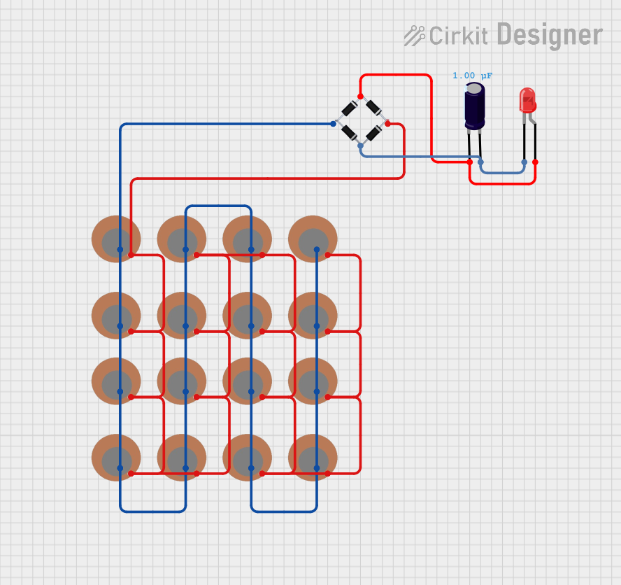
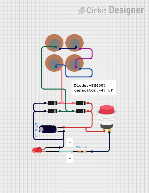
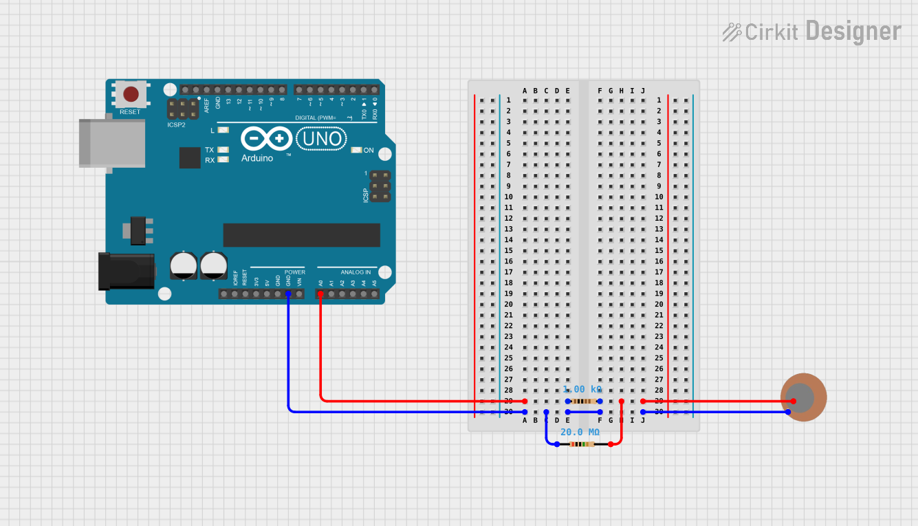
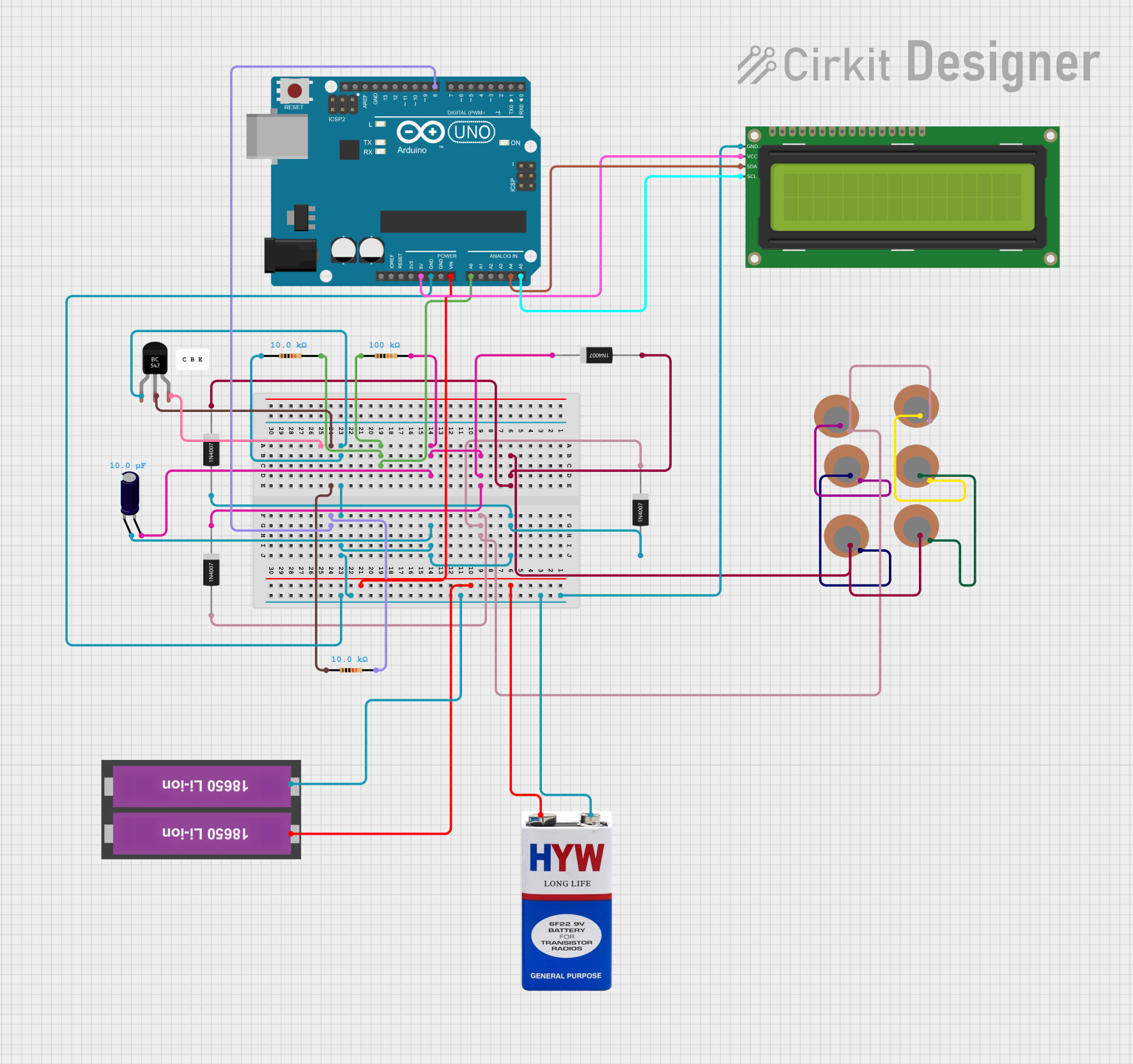
Explore Projects Built with Piezo Sensor
Common Applications and Use Cases
- Electronic drum pads
- Guitar pickups
- Vibration sensing in machinery
- Touch-sensitive user interfaces
- Energy harvesting from mechanical movements
Technical Specifications
Key Technical Details
- Voltage Output: Typically in the millivolt range, varies with pressure applied
- Operating Temperature Range: -20°C to +85°C (may vary by model)
- Sensitivity: Varies with sensor size and material
Pin Configuration and Descriptions
| Pin Number | Description |
|---|---|
| 1 | Signal Output (+) |
| 2 | Ground (-) |
Usage Instructions
How to Use the Component in a Circuit
Connection: Connect the signal output pin to the input of an amplifier or an analog-to-digital converter (ADC) to read the voltage generated by the sensor. The ground pin should be connected to the ground of the circuit.
Signal Conditioning: The output from a piezo sensor is typically a weak signal and may require amplification. Use an operational amplifier (op-amp) for signal conditioning if necessary.
Interfacing with Microcontrollers: When connecting to a microcontroller like an Arduino, ensure that the input pin is configured to read analog voltage.
Important Considerations and Best Practices
- Avoid Excessive Force: Do not apply force exceeding the sensor's maximum rating as it may cause permanent damage.
- Use a Pull-down Resistor: A pull-down resistor may be necessary to ensure a zero voltage reading when no pressure is applied.
- Minimize Noise: Keep the sensor away from sources of electrical noise to prevent false readings.
Example Arduino Code
// Define the pin connected to the Piezo sensor
const int piezoPin = A0;

void setup() {
  // Initialize serial communication at 9600 baud rate
  Serial.begin(9600);
}

void loop() {
  // Read the input on analog pin A0
  int sensorValue = analogRead(piezoPin);

  // Convert the analog reading to voltage (reference voltage is 5V)
  float voltage = sensorValue * (5.0 / 1023.0);

  // Print out the voltage
  Serial.println(voltage);

  // Delay for a bit to avoid spamming the serial output
  delay(100);
}
Troubleshooting and FAQs
Common Issues Users Might Face
- Low Output Voltage: If the output voltage is too low, check the connections and ensure that the sensor is receiving enough force to generate a measurable voltage.
- Inconsistent Readings: Inconsistent readings can be caused by loose connections or electrical noise. Ensure all connections are secure and use shielded cables if necessary.
Solutions and Tips for Troubleshooting
- No Output: If there is no output, verify that the sensor is correctly connected and that the pins are not damaged.
- Noise in Signal: To reduce noise, keep the sensor and wires away from high-frequency devices and consider using a low-pass filter.
FAQs
Q: Can I use a Piezo sensor without an amplifier? A: Yes, for some applications, the raw signal from a Piezo sensor can be read directly by a microcontroller's ADC. However, for precise measurements, an amplifier is recommended.
Q: How do I calibrate my Piezo sensor? A: Calibration involves applying known forces to the sensor and recording the output voltage. Create a calibration curve by plotting the known forces against the measured voltages.
Q: Is the Piezo sensor sensitive to direction? A: Yes, Piezo sensors are typically more sensitive to force applied perpendicular to the surface of the sensor. Forces applied at other angles may result in reduced sensitivity.
Q: Can Piezo sensors be used to generate power? A: Yes, Piezo sensors can be used for energy harvesting from mechanical movements, although the power output is usually small and suitable for low-power applications.