Cirkit Designer Logo
Cirkit Designer
Your all-in-one circuit design IDE
Home / 
Component Documentation

How to Use Infrared Slotted Optical Optocoupler Module: Examples, Pinouts, and Specs

Image of Infrared Slotted Optical Optocoupler Module
Cirkit Designer LogoDesign with Infrared Slotted Optical Optocoupler Module in Cirkit Designer

Introduction

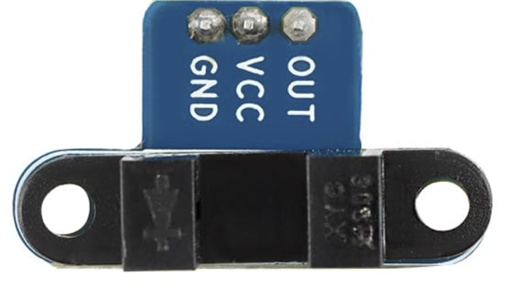
The Infrared Slotted Optical Optocoupler Module is a device that uses infrared light to transmit signals between two electrically isolated circuits. It consists of an infrared emitter (LED) and a photodetector (phototransistor) housed in a slotted enclosure. When an object passes through the slot, it interrupts the infrared light beam, causing a change in the output signal. This module is widely used for non-contact object detection, position sensing, and speed measurement in various applications.

Explore Projects Built with Infrared Slotted Optical Optocoupler Module

Use Cirkit Designer to design, explore, and prototype these projects online. Some projects support real-time simulation. Click "Open Project" to start designing instantly!
Cellular-Connected ESP32-CAM with Real-Time Clock and Isolated Control
Image of LRCM PHASE 2 PRO: A project utilizing Infrared Slotted Optical Optocoupler Module in a practical application
This circuit integrates a LilyGo-SIM7000G module with an RTC DS3231 for timekeeping, interfaced via I2C (SCL and SDA lines). An 8-Channel OPTO-COUPLER is used to isolate and interface external signals with the LilyGo-SIM7000G's GPIOs. Power is managed by a Buck converter, which steps down voltage from a DC Power Source to supply the ESP32-CAM and LilyGo-SIM7000G modules, as well as the OPTO-COUPLER.
Cirkit Designer LogoOpen Project in Cirkit Designer
ESP32-Based Wi-Fi Controlled 24V Input/Output Interface Module
Image of ESP32 4 på rad: A project utilizing Infrared Slotted Optical Optocoupler Module in a practical application
This circuit uses an ESP32 microcontroller to interface with a 3.3V PNP to 24V NPN photoelectric isolation module, which in turn connects to a 40-pin connector for general-purpose input and output. The 24V power supply provides the necessary voltage for the isolation module and the 40-pin connector, enabling the ESP32 to control and monitor high-voltage signals safely.
Cirkit Designer LogoOpen Project in Cirkit Designer
Cellular-Enabled IoT Device with Real-Time Clock and Power Management
Image of LRCM PHASE 2 BASIC: A project utilizing Infrared Slotted Optical Optocoupler Module in a practical application
This circuit features a LilyGo-SIM7000G module for cellular communication and GPS functionality, interfaced with an RTC DS3231 for real-time clock capabilities. It includes voltage sensing through two voltage sensor modules, and uses an 8-channel opto-coupler for isolating different parts of the circuit. Power management is handled by a buck converter connected to a DC power source and batteries, with a fuse for protection and a rocker switch for on/off control. Additionally, there's an LED for indication purposes.
Cirkit Designer LogoOpen Project in Cirkit Designer
Arduino Nano Controlled Octocoupler Interface for Signal Isolation
Image of complete togba no lcd: A project utilizing Infrared Slotted Optical Optocoupler Module in a practical application
This circuit uses optocouplers paired with 220-ohm resistors to interface an Arduino Nano with an external device via a 5-pin relimate connector, providing electrical isolation and signal transfer while protecting the microcontroller. The Arduino's digital I/O pins are connected to the optocouplers, but the control logic is not yet defined in the provided code.
Cirkit Designer LogoOpen Project in Cirkit Designer

Explore Projects Built with Infrared Slotted Optical Optocoupler Module

Use Cirkit Designer to design, explore, and prototype these projects online. Some projects support real-time simulation. Click "Open Project" to start designing instantly!
Image of LRCM PHASE 2 PRO: A project utilizing Infrared Slotted Optical Optocoupler Module in a practical application
Cellular-Connected ESP32-CAM with Real-Time Clock and Isolated Control
This circuit integrates a LilyGo-SIM7000G module with an RTC DS3231 for timekeeping, interfaced via I2C (SCL and SDA lines). An 8-Channel OPTO-COUPLER is used to isolate and interface external signals with the LilyGo-SIM7000G's GPIOs. Power is managed by a Buck converter, which steps down voltage from a DC Power Source to supply the ESP32-CAM and LilyGo-SIM7000G modules, as well as the OPTO-COUPLER.
Cirkit Designer LogoOpen Project in Cirkit Designer
Image of ESP32 4 på rad: A project utilizing Infrared Slotted Optical Optocoupler Module in a practical application
ESP32-Based Wi-Fi Controlled 24V Input/Output Interface Module
This circuit uses an ESP32 microcontroller to interface with a 3.3V PNP to 24V NPN photoelectric isolation module, which in turn connects to a 40-pin connector for general-purpose input and output. The 24V power supply provides the necessary voltage for the isolation module and the 40-pin connector, enabling the ESP32 to control and monitor high-voltage signals safely.
Cirkit Designer LogoOpen Project in Cirkit Designer
Image of LRCM PHASE 2 BASIC: A project utilizing Infrared Slotted Optical Optocoupler Module in a practical application
Cellular-Enabled IoT Device with Real-Time Clock and Power Management
This circuit features a LilyGo-SIM7000G module for cellular communication and GPS functionality, interfaced with an RTC DS3231 for real-time clock capabilities. It includes voltage sensing through two voltage sensor modules, and uses an 8-channel opto-coupler for isolating different parts of the circuit. Power management is handled by a buck converter connected to a DC power source and batteries, with a fuse for protection and a rocker switch for on/off control. Additionally, there's an LED for indication purposes.
Cirkit Designer LogoOpen Project in Cirkit Designer
Image of complete togba no lcd: A project utilizing Infrared Slotted Optical Optocoupler Module in a practical application
Arduino Nano Controlled Octocoupler Interface for Signal Isolation
This circuit uses optocouplers paired with 220-ohm resistors to interface an Arduino Nano with an external device via a 5-pin relimate connector, providing electrical isolation and signal transfer while protecting the microcontroller. The Arduino's digital I/O pins are connected to the optocouplers, but the control logic is not yet defined in the provided code.
Cirkit Designer LogoOpen Project in Cirkit Designer

Common Applications and Use Cases

  • Rotary encoders for speed and position sensing
  • Object detection in automation systems
  • Line-following robots
  • Limit switches in CNC machines
  • Optical tachometers for motor speed measurement

Technical Specifications

The Infrared Slotted Optical Optocoupler Module has the following key specifications:

Parameter Value
Operating Voltage 3.3V to 5V
Output Type Digital (High/Low)
Slot Width 5mm
Infrared Wavelength 940nm
Response Time < 10µs
Operating Temperature -25°C to 85°C
Dimensions Varies by module (e.g., 32mm x 14mm)

Pin Configuration and Descriptions

The module typically has 4 pins, as described in the table below:

Pin Name Description
1 VCC Power supply input (3.3V to 5V)
2 GND Ground connection
3 OUT Digital output signal (High when the slot is clear, Low when the beam is blocked)
4 EN (optional) Enable pin (used to enable or disable the module, depending on the design)

Usage Instructions

How to Use the Component in a Circuit

  1. Power the Module: Connect the VCC pin to a 3.3V or 5V power source and the GND pin to the ground of your circuit.
  2. Connect the Output: Connect the OUT pin to a digital input pin of your microcontroller or other logic circuit.
  3. Position the Module: Place the module so that the object to be detected can pass through the slot, interrupting the infrared beam.
  4. Read the Output: Monitor the OUT pin. It will output a HIGH signal when the slot is clear and a LOW signal when the beam is blocked.

Important Considerations and Best Practices

  • Alignment: Ensure proper alignment of the object with the slot for accurate detection.
  • Debouncing: If the module is used for high-speed applications, consider implementing software or hardware debouncing to filter out noise.
  • Power Supply: Use a stable power supply to avoid fluctuations in the output signal.
  • Ambient Light: Avoid placing the module in direct sunlight or near strong infrared sources, as this may interfere with its operation.

Example: Connecting to an Arduino UNO

Below is an example of how to use the Infrared Slotted Optical Optocoupler Module with an Arduino UNO to detect objects passing through the slot.

Circuit Connections

  • Connect the VCC pin of the module to the 5V pin of the Arduino.
  • Connect the GND pin of the module to the GND pin of the Arduino.
  • Connect the OUT pin of the module to digital pin 2 of the Arduino.

Arduino Code

// Infrared Slotted Optical Optocoupler Module Example
// This code reads the output of the module and prints the status to the Serial Monitor.

const int sensorPin = 2; // Pin connected to the OUT pin of the module
int sensorState = 0;     // Variable to store the sensor state

void setup() {
  pinMode(sensorPin, INPUT); // Set the sensor pin as input
  Serial.begin(9600);        // Initialize serial communication at 9600 baud
}

void loop() {
  sensorState = digitalRead(sensorPin); // Read the sensor output

  if (sensorState == HIGH) {
    // If the slot is clear, the output is HIGH
    Serial.println("Slot is clear");
  } else {
    // If the beam is blocked, the output is LOW
    Serial.println("Beam is blocked");
  }

  delay(100); // Small delay to avoid flooding the Serial Monitor
}

Troubleshooting and FAQs

Common Issues and Solutions

  1. No Output Signal

    • Cause: Incorrect wiring or loose connections.
    • Solution: Double-check all connections, ensuring the VCC and GND pins are properly connected.
  2. False Triggering

    • Cause: Ambient light interference or electrical noise.
    • Solution: Shield the module from strong light sources and use a decoupling capacitor near the power pins.
  3. Slow Response

    • Cause: High capacitance on the output line or software delays.
    • Solution: Minimize capacitance and optimize the code for faster response.
  4. Output Always HIGH or LOW

    • Cause: Misalignment of the object or a damaged module.
    • Solution: Ensure proper alignment and test the module with a known working setup.

FAQs

Q: Can this module detect transparent objects?
A: No, the module is not suitable for detecting transparent objects, as they may not sufficiently block the infrared beam.

Q: What is the maximum detection speed?
A: The module has a response time of less than 10µs, making it suitable for high-speed applications.

Q: Can I use this module with a 3.3V microcontroller?
A: Yes, the module operates within a voltage range of 3.3V to 5V, making it compatible with 3.3V systems.

Q: How do I extend the detection range?
A: The detection range is fixed by the slot width. For longer ranges, consider using a reflective or through-beam optocoupler instead.