How to Use Strain Gauge: Examples, Pinouts, and Specs
Introduction
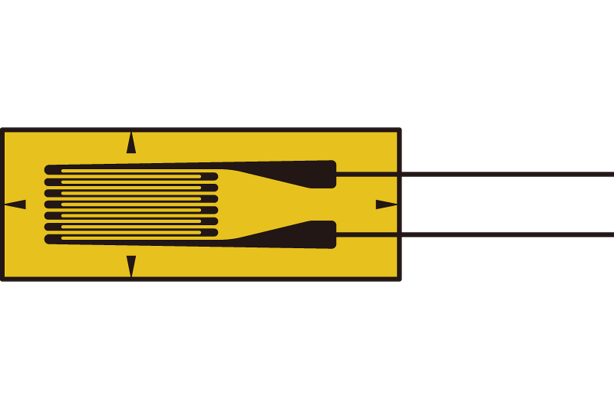
A strain gauge is a sensor used to measure the amount of deformation or strain in an object. It operates on the principle that the electrical resistance of a conductor changes when it is stretched or compressed. Strain gauges are widely used in mechanical engineering, structural monitoring, and material testing to measure stress, force, or pressure indirectly by detecting strain.
Explore Projects Built with Strain Gauge
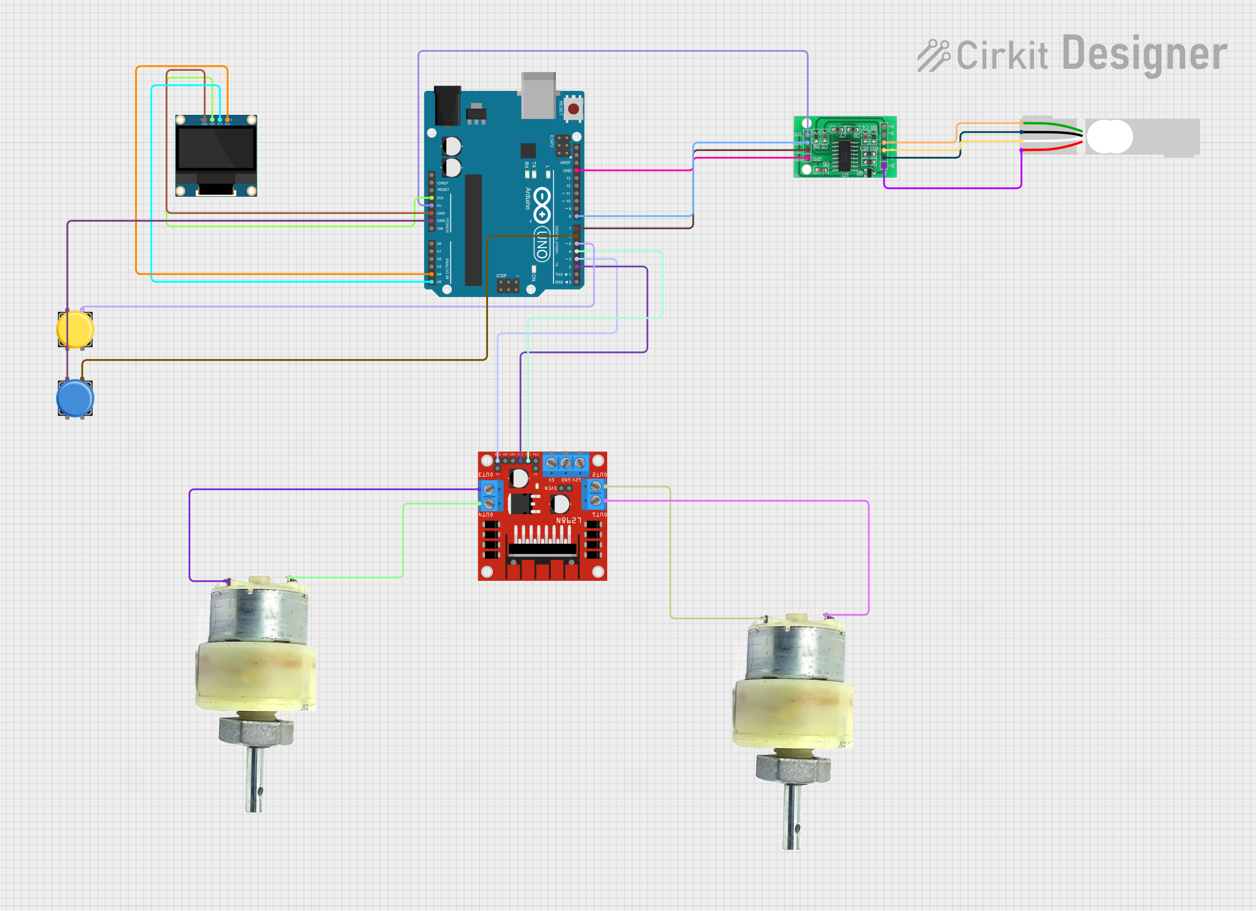

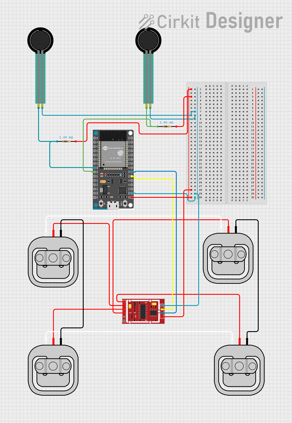
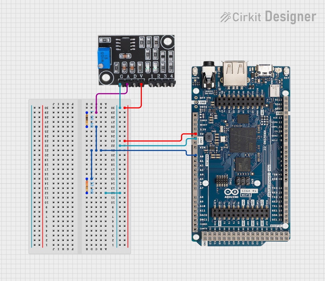
Explore Projects Built with Strain Gauge
Common Applications and Use Cases
- Structural Health Monitoring: Measuring strain in bridges, buildings, and other structures.
- Load Cells: Used in weighing scales to measure force or weight.
- Material Testing: Evaluating the mechanical properties of materials under stress.
- Robotics: Monitoring forces in robotic arms and grippers.
- Aerospace and Automotive: Measuring stress in components under dynamic conditions.
Technical Specifications
Below are the key technical details of a typical strain gauge:
| Parameter | Value |
|---|---|
| Gauge Factor (GF) | 2.0 (typical) |
| Resistance | 120 Ω, 350 Ω, or 1 kΩ (common) |
| Operating Temperature | -40°C to +150°C |
| Strain Range | ±5% strain |
| Accuracy | ±0.1% of full-scale output |
| Material | Foil, semiconductor, or wire |
Pin Configuration and Descriptions
Strain gauges typically do not have "pins" like integrated circuits but are connected via terminals or solder pads. Below is a description of the connections:
| Connection | Description |
|---|---|
| Positive Lead | Connects to the positive terminal of the Wheatstone bridge or signal amplifier. |
| Negative Lead | Connects to the negative terminal of the Wheatstone bridge or signal amplifier. |
| Substrate | The backing material that supports the strain gauge (not an electrical connection). |
Usage Instructions
How to Use the Strain Gauge in a Circuit
- Prepare the Surface: Ensure the surface where the strain gauge will be mounted is clean, smooth, and free of contaminants.
- Mount the Strain Gauge: Use a suitable adhesive (e.g., cyanoacrylate) to attach the strain gauge to the surface. Allow the adhesive to cure fully.
- Connect to a Wheatstone Bridge:
- Strain gauges are typically used in a Wheatstone bridge configuration to measure small changes in resistance.
- Connect the strain gauge as one of the resistive elements in the bridge.
- Amplify the Signal:
- The output of the Wheatstone bridge is a small voltage signal proportional to the strain.
- Use an instrumentation amplifier (e.g., INA125) to amplify the signal for further processing.
- Read the Output:
- The amplified signal can be read using an analog-to-digital converter (ADC) or a microcontroller.
Important Considerations and Best Practices
- Temperature Compensation: Strain gauges are sensitive to temperature changes. Use a dummy strain gauge in the Wheatstone bridge for compensation.
- Calibration: Calibrate the system to ensure accurate strain measurements.
- Adhesive Selection: Choose an adhesive that matches the operating environment (e.g., high temperature, humidity).
- Shielding: Use shielded cables to minimize noise interference in the signal.
Example: Connecting a Strain Gauge to an Arduino UNO
Below is an example of how to connect a strain gauge to an Arduino UNO using an HX711 load cell amplifier module:
Circuit Diagram
- Connect the strain gauge to the HX711 module as per the module's instructions.
- Connect the HX711 module to the Arduino UNO:
VCCto5VGNDtoGNDDTtoD3SCKtoD2
Arduino Code
#include "HX711.h"

// Define pins for HX711 module
#define DT 3  // Data pin connected to Arduino digital pin 3
#define SCK 2 // Clock pin connected to Arduino digital pin 2

HX711 scale;

void setup() {
  Serial.begin(9600); // Initialize serial communication
  scale.begin(DT, SCK); // Initialize HX711 with defined pins
  scale.set_scale();    // Set the scale factor (calibration required)
  scale.tare();         // Reset the scale to zero
  Serial.println("Strain Gauge Ready");
}

void loop() {
  // Read the weight/strain value
  float strainValue = scale.get_units(10); // Average of 10 readings
  Serial.print("Strain Value: ");
  Serial.println(strainValue); // Print the strain value to the serial monitor
  delay(500); // Wait for 500ms before the next reading
}
Note: The
set_scale()function requires calibration. Replace the default value with the appropriate scale factor for your setup.
Troubleshooting and FAQs
Common Issues and Solutions
No Output Signal:
- Cause: Loose connections or incorrect wiring.
- Solution: Verify all connections, especially between the strain gauge, Wheatstone bridge, and amplifier.
Inconsistent Readings:
- Cause: Poor adhesive bonding or environmental noise.
- Solution: Ensure proper mounting and use shielded cables to reduce noise.
Temperature Drift:
- Cause: Temperature changes affecting the strain gauge resistance.
- Solution: Use a temperature-compensated Wheatstone bridge configuration.
Low Signal Output:
- Cause: Insufficient amplification.
- Solution: Check the gain settings of the amplifier and ensure proper calibration.
FAQs
Q: Can I use a strain gauge without a Wheatstone bridge?
A: No, strain gauges require a Wheatstone bridge to detect small resistance changes accurately.Q: How do I calibrate a strain gauge system?
A: Apply a known force or strain to the system and adjust the scale factor in the software until the output matches the expected value.Q: What adhesive should I use for mounting?
A: Use a high-quality adhesive like cyanoacrylate or epoxy, depending on the operating environment.Q: Can I use multiple strain gauges in one system?
A: Yes, you can use multiple strain gauges in a full-bridge or half-bridge configuration for enhanced sensitivity and temperature compensation.