How to Use ESP32 (30 pin): Examples, Pinouts, and Specs
Introduction
The ESP32 (30 pin) is a powerful microcontroller designed for IoT and embedded system applications. It features built-in Wi-Fi and Bluetooth capabilities, making it an excellent choice for projects requiring wireless communication. With its 30 GPIO pins, the ESP32 offers a wide range of input/output functions, including ADC, DAC, PWM, I2C, SPI, and UART, making it versatile for various applications.
Explore Projects Built with ESP32 (30 pin)


Explore Projects Built with ESP32 (30 pin)
Common Applications and Use Cases
- IoT devices and smart home automation
- Wireless sensor networks
- Wearable technology
- Robotics and automation systems
- Data logging and remote monitoring
- Prototyping and educational projects
Technical Specifications
Key Technical Details
- Microcontroller: Tensilica Xtensa LX6 dual-core processor
- Clock Speed: Up to 240 MHz
- Flash Memory: 4 MB (varies by model)
- SRAM: 520 KB
- Wi-Fi: 802.11 b/g/n
- Bluetooth: v4.2 BR/EDR and BLE
- Operating Voltage: 3.3V
- Input Voltage Range: 5V (via USB) or 7-12V (via VIN pin)
- GPIO Pins: 30 (multipurpose, including ADC, DAC, PWM, I2C, SPI, UART)
- ADC Resolution: 12-bit
- DAC Resolution: 8-bit
- Power Consumption: Ultra-low power consumption in deep sleep mode (~10 µA)
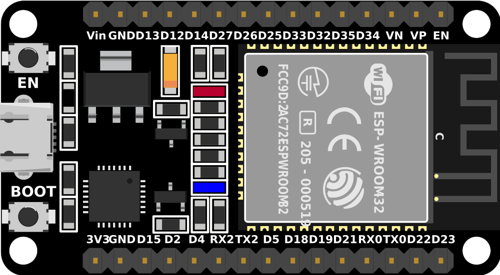
Pin Configuration and Descriptions
The ESP32 (30 pin) has the following pinout:
| Pin Name | Function | Description |
|---|---|---|
| VIN | Power Input | Accepts 7-12V input to power the ESP32. |
| GND | Ground | Common ground for the circuit. |
| 3V3 | Power Output | Provides 3.3V output for external components. |
| EN | Enable | Enables or disables the chip (active high). |
| IO0 | GPIO0 / Boot Mode | General-purpose I/O pin; used for boot mode selection during programming. |
| IO1 (TX0) | GPIO1 / UART TX | UART transmit pin; also used as GPIO. |
| IO3 (RX0) | GPIO3 / UART RX | UART receive pin; also used as GPIO. |
| IO4 | GPIO4 | General-purpose I/O pin. |
| IO5 | GPIO5 | General-purpose I/O pin. |
| IO12 | GPIO12 / ADC2_5 / Touch5 | General-purpose I/O, ADC, or capacitive touch input. |
| IO13 | GPIO13 / ADC2_4 / Touch4 | General-purpose I/O, ADC, or capacitive touch input. |
| IO14 | GPIO14 / ADC2_6 / Touch6 | General-purpose I/O, ADC, or capacitive touch input. |
| IO15 | GPIO15 / ADC2_3 / Touch3 | General-purpose I/O, ADC, or capacitive touch input. |
| IO16 | GPIO16 | General-purpose I/O pin. |
| IO17 | GPIO17 | General-purpose I/O pin. |
| IO18 | GPIO18 / SPI_CLK | General-purpose I/O or SPI clock pin. |
| IO19 | GPIO19 / SPI_MISO | General-purpose I/O or SPI MISO pin. |
| IO21 | GPIO21 / I2C SDA | General-purpose I/O or I2C data pin. |
| IO22 | GPIO22 / I2C SCL | General-purpose I/O or I2C clock pin. |
| IO23 | GPIO23 / SPI_MOSI | General-purpose I/O or SPI MOSI pin. |
| IO25 | GPIO25 / DAC1 / ADC2_8 | General-purpose I/O, DAC, or ADC pin. |
| IO26 | GPIO26 / DAC2 / ADC2_9 | General-purpose I/O, DAC, or ADC pin. |
| IO27 | GPIO27 / ADC2_7 / Touch7 | General-purpose I/O, ADC, or capacitive touch input. |
| IO32 | GPIO32 / ADC1_4 / Touch9 | General-purpose I/O, ADC, or capacitive touch input. |
| IO33 | GPIO33 / ADC1_5 / Touch8 | General-purpose I/O, ADC, or capacitive touch input. |
| IO34 | GPIO34 / ADC1_6 | Input-only ADC pin. |
| IO35 | GPIO35 / ADC1_7 | Input-only ADC pin. |
Usage Instructions
How to Use the ESP32 in a Circuit
Powering the ESP32:
- Use the VIN pin to supply 7-12V, or connect a 5V USB power source.
- Ensure the GND pin is connected to the common ground of your circuit.
Programming the ESP32:
- Use a USB cable to connect the ESP32 to your computer.
- Install the ESP32 board package in the Arduino IDE or use the ESP-IDF framework.
- Select the correct board and port in the IDE before uploading code.
Connecting Peripherals:
- Use GPIO pins for digital or analog input/output.
- For communication protocols, connect devices to the appropriate pins (e.g., I2C, SPI, UART).
Wi-Fi and Bluetooth Setup:
- Use the built-in libraries (e.g.,
WiFi.horBluetoothSerial.h) to configure wireless communication.
- Use the built-in libraries (e.g.,
Important Considerations and Best Practices
- Voltage Levels: The ESP32 operates at 3.3V logic levels. Avoid connecting 5V signals directly to GPIO pins.
- Boot Mode: Ensure GPIO0 is pulled low during programming to enter boot mode.
- Power Supply: Use a stable power source to avoid unexpected resets or instability.
- Deep Sleep: Utilize deep sleep mode for low-power applications to extend battery life.
Example Code for Arduino IDE
The following example demonstrates how to connect the ESP32 to a Wi-Fi network and blink an LED:
#include <WiFi.h> // Include the Wi-Fi library

const char* ssid = "Your_SSID";       // Replace with your Wi-Fi network name
const char* password = "Your_Password"; // Replace with your Wi-Fi password
const int ledPin = 2;                 // GPIO2 is typically connected to the onboard LED

void setup() {
  pinMode(ledPin, OUTPUT);            // Set the LED pin as an output
  Serial.begin(115200);               // Start the serial communication
  WiFi.begin(ssid, password);         // Connect to the Wi-Fi network

  Serial.print("Connecting to Wi-Fi");
  while (WiFi.status() != WL_CONNECTED) {
    delay(500);
    Serial.print(".");
  }
  Serial.println("\nConnected to Wi-Fi!");
}

void loop() {
  digitalWrite(ledPin, HIGH);         // Turn the LED on
  delay(1000);                        // Wait for 1 second
  digitalWrite(ledPin, LOW);          // Turn the LED off
  delay(1000);                        // Wait for 1 second
}
Troubleshooting and FAQs
Common Issues and Solutions
ESP32 Not Connecting to Wi-Fi:
- Double-check the SSID and password in your code.
- Ensure the Wi-Fi network is active and within range.
- Restart the ESP32 and router if necessary.
Upload Fails or Timeout Errors:
- Ensure the correct board and port are selected in the Arduino IDE.
- Hold the BOOT button while uploading to force boot mode.
- Check the USB cable and connection.
ESP32 Keeps Resetting:
- Verify the power supply is stable and sufficient.
- Avoid excessive current draw from GPIO pins.
GPIO Pin Not Working:
- Confirm the pin is not reserved for internal functions (e.g., GPIO0, GPIO2 during boot).
- Check for short circuits or incorrect wiring.
FAQs
Can the ESP32 handle 5V logic?
No, the ESP32 operates at 3.3V logic levels. Use a level shifter for 5V signals.How do I use the ESP32's Bluetooth?
Use theBluetoothSeriallibrary in the Arduino IDE to configure and communicate via Bluetooth.What is the maximum number of devices the ESP32 can connect to via Wi-Fi?
The ESP32 can act as a Wi-Fi access point and support up to 10 devices by default, but this can be increased with custom configurations.How do I reduce power consumption?
Use deep sleep mode and disable unused peripherals to minimize power usage.