Cirkit Designer Logo
Cirkit Designer
Your all-in-one circuit design IDE
Home / 
Component Documentation

How to Use SIM900A: Examples, Pinouts, and Specs

Image of SIM900A
Cirkit Designer LogoDesign with SIM900A in Cirkit Designer

Introduction

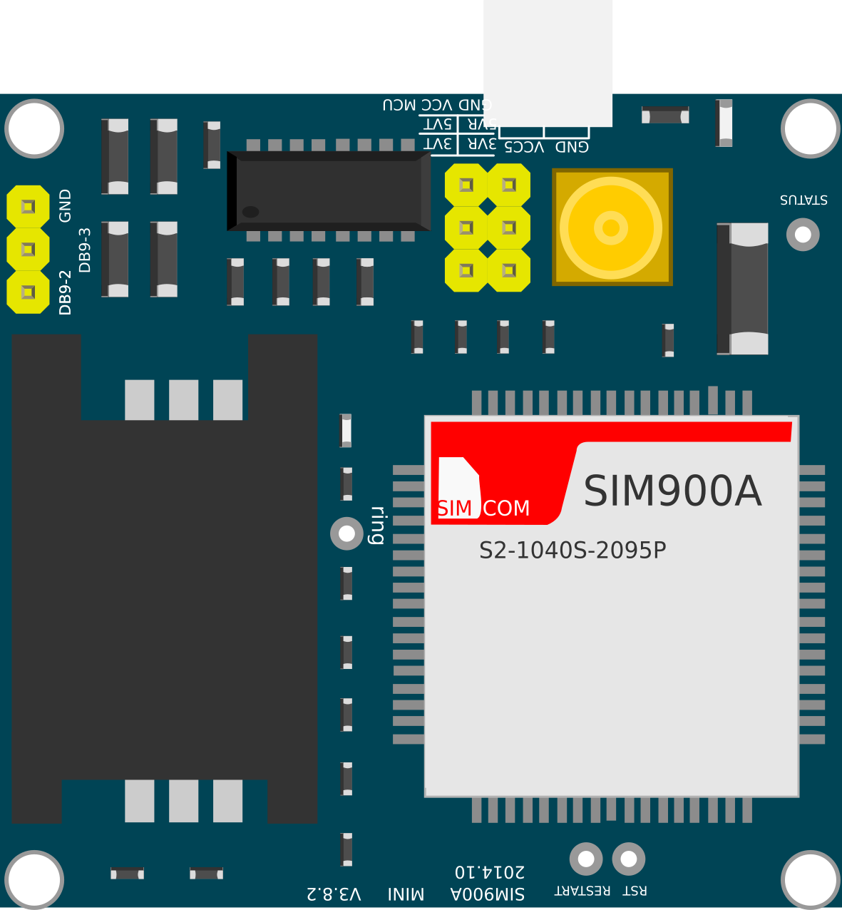
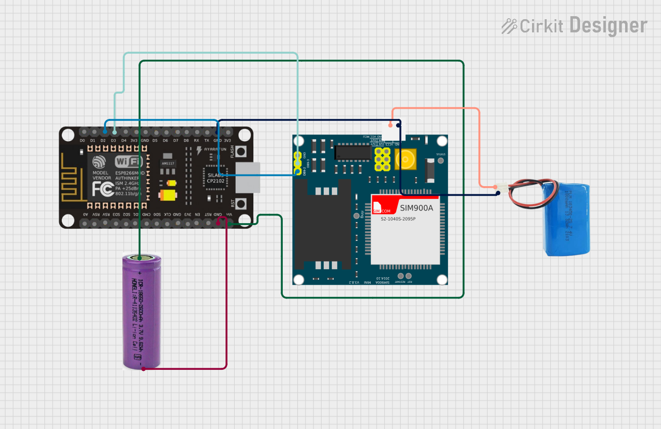
The SIM900A is a complete Dual-band GSM/GPRS solution in a compact plug-in module. Featuring an industry-standard interface, the SIM900A delivers GSM/GPRS 900/1800MHz performance for voice, SMS, Data, and Fax in a small form factor and with low power consumption. It is ideal for a wide range of products including IoT devices, system monitoring, and many other communication systems.

Explore Projects Built with SIM900A

Use Cirkit Designer to design, explore, and prototype these projects online. Some projects support real-time simulation. Click "Open Project" to start designing instantly!
Arduino UNO and SIM900A GSM Module Communication System
Image of srp: A project utilizing SIM900A in a practical application
This circuit interfaces an Arduino UNO with a SIM900A GSM module. The Arduino communicates with the SIM900A via digital pins D9 and D10 for serial data transmission and reception, while both devices share a common ground.
Cirkit Designer LogoOpen Project in Cirkit Designer
Arduino UNO and SIM900A GSM Module for Remote Communication
Image of gsmsim900A_ardunio: A project utilizing SIM900A in a practical application
This circuit interfaces an Arduino UNO with a SIM900A GSM module. The Arduino controls the SIM900A via digital pins D9 and D10 for serial communication, while both components share a common ground.
Cirkit Designer LogoOpen Project in Cirkit Designer
Arduino UNO and SIM900A GSM Module for Remote Communication
Image of gsm: A project utilizing SIM900A in a practical application
This circuit integrates an Arduino UNO with a SIM900A GSM module, powered by a 12V power supply. The Arduino communicates with the SIM900A via digital pins D4 and D5 for TX and RX respectively, enabling GSM communication capabilities.
Cirkit Designer LogoOpen Project in Cirkit Designer
ESP8266 NodeMCU with SIM900A GSM Module for SMS and Call Functions
Image of Project interface: A project utilizing SIM900A in a practical application
This circuit connects an ESP8266 NodeMCU microcontroller to a SIM900A GSM/GPRS module, enabling cellular communication capabilities such as making calls, sending SMS, and receiving messages. The ESP8266 is powered by a 3.3V battery connected to its VIN pin, while the SIM900A is powered by a separate 5V battery. The microcontroller uses software serial communication to interface with the SIM900A module, with the ESP8266's D2 and D3 pins connected to the SIM900A's TXD and RXD pins, respectively.
Cirkit Designer LogoOpen Project in Cirkit Designer

Explore Projects Built with SIM900A

Use Cirkit Designer to design, explore, and prototype these projects online. Some projects support real-time simulation. Click "Open Project" to start designing instantly!
Image of srp: A project utilizing SIM900A in a practical application
Arduino UNO and SIM900A GSM Module Communication System
This circuit interfaces an Arduino UNO with a SIM900A GSM module. The Arduino communicates with the SIM900A via digital pins D9 and D10 for serial data transmission and reception, while both devices share a common ground.
Cirkit Designer LogoOpen Project in Cirkit Designer
Image of gsmsim900A_ardunio: A project utilizing SIM900A in a practical application
Arduino UNO and SIM900A GSM Module for Remote Communication
This circuit interfaces an Arduino UNO with a SIM900A GSM module. The Arduino controls the SIM900A via digital pins D9 and D10 for serial communication, while both components share a common ground.
Cirkit Designer LogoOpen Project in Cirkit Designer
Image of gsm: A project utilizing SIM900A in a practical application
Arduino UNO and SIM900A GSM Module for Remote Communication
This circuit integrates an Arduino UNO with a SIM900A GSM module, powered by a 12V power supply. The Arduino communicates with the SIM900A via digital pins D4 and D5 for TX and RX respectively, enabling GSM communication capabilities.
Cirkit Designer LogoOpen Project in Cirkit Designer
Image of Project interface: A project utilizing SIM900A in a practical application
ESP8266 NodeMCU with SIM900A GSM Module for SMS and Call Functions
This circuit connects an ESP8266 NodeMCU microcontroller to a SIM900A GSM/GPRS module, enabling cellular communication capabilities such as making calls, sending SMS, and receiving messages. The ESP8266 is powered by a 3.3V battery connected to its VIN pin, while the SIM900A is powered by a separate 5V battery. The microcontroller uses software serial communication to interface with the SIM900A module, with the ESP8266's D2 and D3 pins connected to the SIM900A's TXD and RXD pins, respectively.
Cirkit Designer LogoOpen Project in Cirkit Designer

Common Applications and Use Cases

  • Mobile phones
  • IoT devices
  • Remote data monitoring
  • SMS-based alert systems
  • Voice communication systems

Technical Specifications

Key Technical Details

  • Dual-Band 900/ 1800 MHz
  • GPRS multi-slot class 10/8
  • GPRS mobile station class B
  • Compliant to GSM phase 2/2+
  • Class 4 (2 W @ 900 MHz)
  • Class 1 (1 W @ 1800MHz)

Pin Configuration and Descriptions

Pin Number Name Description
1 VCC Power supply
2 RST Reset pin
3 RXD Serial data receive pin
4 TXD Serial data transmit pin
5 GND Ground connection

Usage Instructions

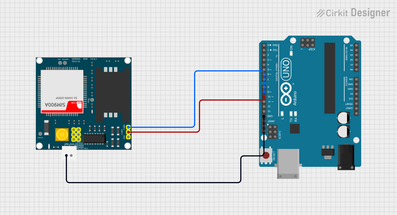
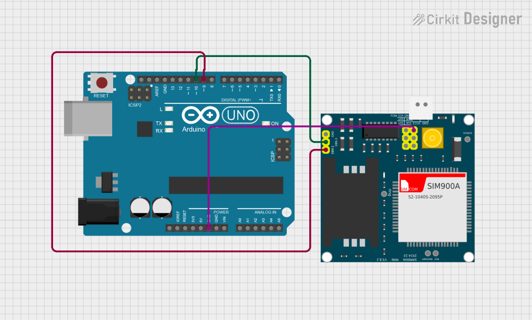
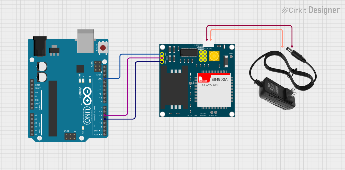
How to Use the SIM900A in a Circuit

  1. Power Supply: Connect a 3.4V to 4.5V power supply to the VCC and GND pins. Ensure that the power supply can deliver up to 2A during transmission bursts.

  2. Serial Communication: Connect the RXD and TXD pins to a microcontroller or computer's UART interface. Remember that the SIM900A operates at TTL logic levels.

  3. Antenna: Attach a suitable GSM antenna to the module for proper communication.

  4. SIM Card: Insert a SIM card into the SIM card holder.

Important Considerations and Best Practices

  • Ensure that the power supply is stable and can handle the current requirements.
  • Use a level shifter if the microcontroller operates at a different logic level than the SIM900A.
  • Place the antenna away from metal objects and electronic devices to minimize interference.
  • Follow all ESD precautions when handling the module to prevent damage.

Example Code for Arduino UNO

#include <SoftwareSerial.h>

SoftwareSerial SIM900A(7, 8); // RX, TX

void setup() {
  // Begin serial communication with Arduino and Arduino IDE (Serial Monitor)
  Serial.begin(9600);
  
  // Begin serial communication with SIM900A and set baud rate
  SIM900A.begin(9600);
  
  // Check if SIM900A is working
  Serial.println("Setting up SIM900A...");
  delay(1000); // Give time for module to stabilize
  SIM900A.println("AT"); // Send AT command to SIM900A
}

void loop() {
  // Forward every message from SIM900A to the Serial Monitor
  if (SIM900A.available()) {
    Serial.write(SIM900A.read());
  }
  // Forward every message from the Serial Monitor to SIM900A
  if (Serial.available()) {
    SIM900A.write(Serial.read());
  }
}

Troubleshooting and FAQs

Common Issues Users Might Face

  • Power Issues: If the SIM900A does not power up, check the power supply and connections.
  • Signal Problems: Poor signal quality can affect communication. Ensure the antenna is properly connected and placed.
  • SIM Card Not Recognized: Make sure the SIM card is inserted correctly and is activated.

Solutions and Tips for Troubleshooting

  • Power Supply: Use a power supply that can deliver a high transient current to avoid brown-out conditions.
  • Baud Rate: Ensure the baud rate of the SIM900A matches the baud rate of the microcontroller's UART.
  • AT Commands: Use AT commands to communicate with the SIM900A and check its status.

FAQs

Q: What is the default baud rate of the SIM900A? A: The default baud rate is typically set to 9600 bps.

Q: Can I use the SIM900A for internet connectivity? A: Yes, the SIM900A supports GPRS for internet connectivity, but it is limited to 2G speeds.

Q: How can I reduce power consumption of the SIM900A? A: Utilize the power-down mode and control the sleep level via AT commands.

Q: What should I do if I can't communicate with the SIM900A? A: Double-check your wiring, ensure correct power supply, and verify that the SIM card is working and has credit.

This documentation provides a comprehensive guide to the SIM900A GSM/GPRS module, ensuring users can effectively integrate it into their projects. For further assistance, consult the SIM900A datasheet and application notes provided by the manufacturer.