How to Use Dc Auto Transfer Switch: Examples, Pinouts, and Specs
Introduction
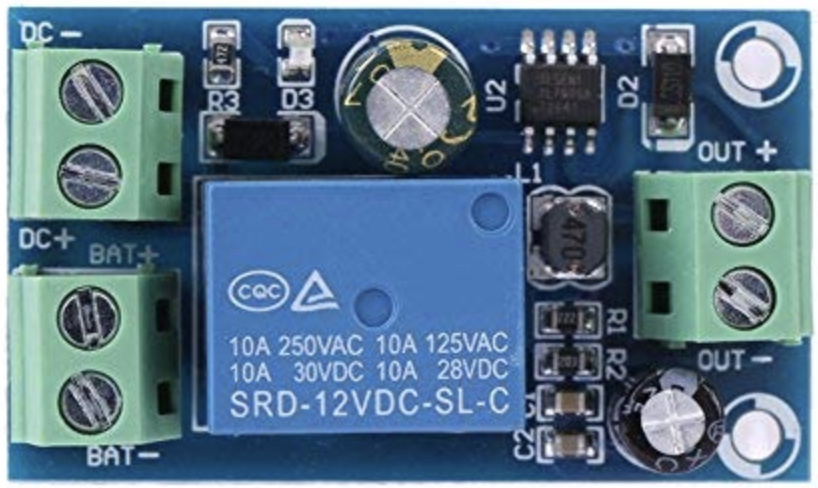
The DC Auto Transfer Switch is a device designed to automatically switch the power supply between two DC sources, ensuring uninterrupted power delivery to connected loads. This component is particularly useful in systems where continuous power availability is critical, such as renewable energy systems, backup power setups, and industrial automation. By seamlessly transferring power between sources, the DC Auto Transfer Switch protects against power interruptions and ensures system reliability.
Explore Projects Built with Dc Auto Transfer Switch
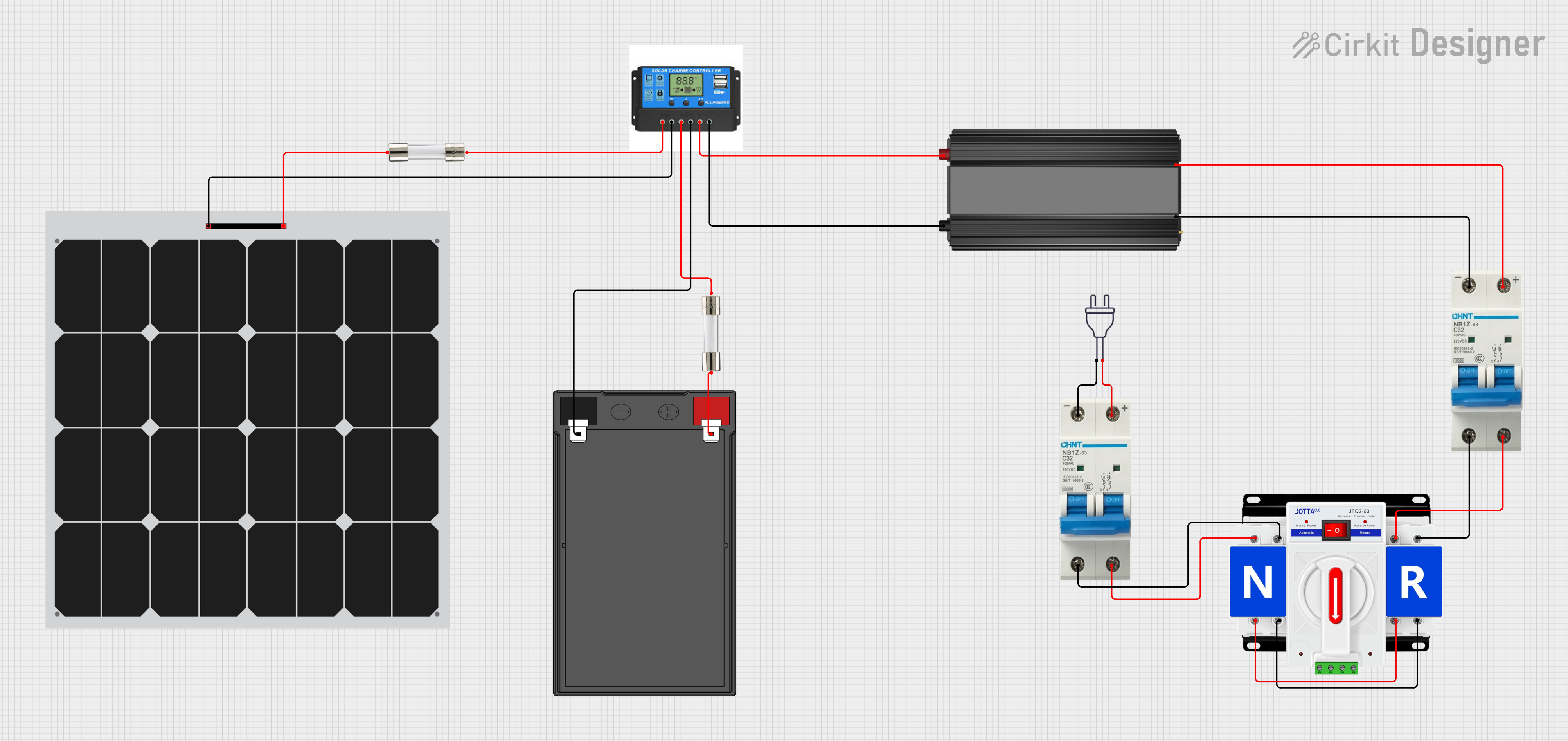


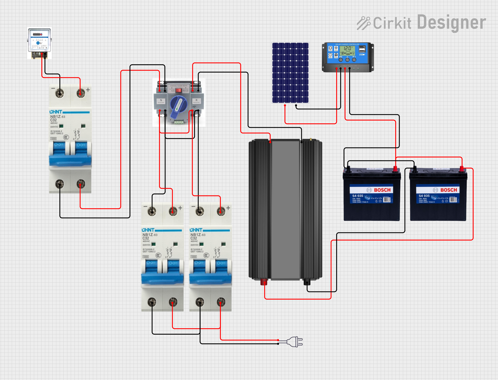
Explore Projects Built with Dc Auto Transfer Switch
Common Applications and Use Cases
- Solar power systems with battery backups
- Uninterruptible power supply (UPS) systems
- Industrial automation and control systems
- Telecommunications equipment
- Emergency lighting systems
- Off-grid renewable energy setups
Technical Specifications
Key Technical Details
| Parameter | Value |
|---|---|
| Operating Voltage Range | 12V DC to 48V DC |
| Maximum Current Rating | 30A |
| Switching Time | < 10ms |
| Power Source Inputs | 2 (Primary and Secondary) |
| Output Channels | 1 |
| Control Method | Automatic |
| Operating Temperature Range | -20°C to 60°C |
| Dimensions | 100mm x 60mm x 40mm |
| Weight | 150g |
Pin Configuration and Descriptions
| Pin Name | Description |
|---|---|
| Primary Input | Connects to the primary DC power source (e.g., solar panel or main battery). |
| Secondary Input | Connects to the secondary DC power source (e.g., backup battery). |
| Output | Provides the switched DC output to the load. |
| Ground (GND) | Common ground connection for the circuit. |
Usage Instructions
How to Use the Component in a Circuit
Connect the Power Sources:
- Attach the primary DC power source to the
Primary Inputpin. - Attach the backup DC power source to the
Secondary Inputpin. - Ensure both sources are within the operating voltage range (12V to 48V DC).
- Attach the primary DC power source to the
Connect the Load:
- Connect the load (e.g., DC motor, LED lights, or other devices) to the
Outputpin. - Ensure the load does not exceed the maximum current rating of 30A.
- Connect the load (e.g., DC motor, LED lights, or other devices) to the
Grounding:
- Connect the
Ground (GND)pin to the common ground of the circuit.
- Connect the
Power On:
- Power on the primary and secondary sources. The switch will automatically prioritize the primary source.
- If the primary source fails, the switch will transfer to the secondary source within 10ms.
Important Considerations and Best Practices
- Voltage Compatibility: Ensure both power sources are within the specified operating voltage range.
- Current Rating: Do not exceed the maximum current rating of 30A to avoid damage to the switch.
- Heat Dissipation: Install the switch in a well-ventilated area to prevent overheating.
- Polarity: Double-check the polarity of all connections to avoid short circuits or damage.
- Testing: Before connecting sensitive equipment, test the switch operation with a dummy load.
Example: Using with an Arduino UNO
While the DC Auto Transfer Switch operates independently, it can be monitored using an Arduino UNO to detect which power source is active. Below is an example code snippet:
// Example code to monitor the active power source of a DC Auto Transfer Switch
// Connect the status pins of the switch to Arduino digital pins 2 and 3

const int primaryStatusPin = 2;  // Pin connected to the primary source status
const int secondaryStatusPin = 3; // Pin connected to the secondary source status

void setup() {
  pinMode(primaryStatusPin, INPUT);  // Set primary status pin as input
  pinMode(secondaryStatusPin, INPUT); // Set secondary status pin as input
  Serial.begin(9600);  // Initialize serial communication
}

void loop() {
  bool primaryActive = digitalRead(primaryStatusPin);  // Read primary source status
  bool secondaryActive = digitalRead(secondaryStatusPin); // Read secondary source status

  if (primaryActive) {
    Serial.println("Primary power source is active.");
  } else if (secondaryActive) {
    Serial.println("Secondary power source is active.");
  } else {
    Serial.println("No power source is active!");
  }

  delay(1000);  // Wait for 1 second before checking again
}
Troubleshooting and FAQs
Common Issues and Solutions
Switch Does Not Transfer to Secondary Source:
- Cause: Secondary source voltage is outside the operating range.
- Solution: Verify the voltage of the secondary source and ensure it is between 12V and 48V DC.
Load Does Not Receive Power:
- Cause: Incorrect wiring or loose connections.
- Solution: Double-check all connections, ensuring proper polarity and secure contacts.
Overheating:
- Cause: Excessive current draw or poor ventilation.
- Solution: Ensure the load does not exceed 30A and install the switch in a well-ventilated area.
Switching Delay is Too Long:
- Cause: Faulty internal components or power source instability.
- Solution: Test the power sources for stability and replace the switch if necessary.
FAQs
Q1: Can the DC Auto Transfer Switch handle AC power?
A1: No, this switch is designed specifically for DC circuits. Using it with AC power may damage the device.
Q2: What happens if both power sources fail?
A2: If both sources fail, the switch will not provide power to the load. Ensure at least one source is always operational.
Q3: Can I use this switch with a solar panel and a battery?
A3: Yes, the switch is ideal for such setups. Connect the solar panel as the primary source and the battery as the secondary source.
Q4: Is manual control possible?
A4: No, this switch operates automatically and does not support manual control.
By following this documentation, you can effectively integrate the DC Auto Transfer Switch into your projects and ensure reliable power delivery.