Cirkit Designer Logo
Cirkit Designer
Your all-in-one circuit design IDE
Home / 
Component Documentation

How to Use RS485 to TTL Converter: Examples, Pinouts, and Specs

Image of RS485 to TTL Converter
Cirkit Designer LogoDesign with RS485 to TTL Converter in Cirkit Designer

Introduction

The RS485 to TTL Converter is a versatile device designed to bridge the gap between RS485 serial communication signals and TTL (Transistor-Transistor Logic) levels. RS485 is a widely used communication standard in industrial and embedded systems due to its long-distance communication capability and noise immunity. This converter enables seamless communication between RS485 devices and microcontrollers, such as Arduino, Raspberry Pi, or other TTL-compatible devices.

Explore Projects Built with RS485 to TTL Converter

Use Cirkit Designer to design, explore, and prototype these projects online. Some projects support real-time simulation. Click "Open Project" to start designing instantly!
Arduino UNO and Relay-Controlled RS485 Communication System
Image of Diagrama: A project utilizing RS485 to TTL Converter in a practical application
This circuit features an Arduino UNO microcontroller interfaced with a 4-channel relay module and a UART TTL to RS485 converter. The Arduino controls the relays via digital pins and communicates with the RS485 converter for serial communication, enabling control of external devices and communication over long distances.
Cirkit Designer LogoOpen Project in Cirkit Designer
ESP32-Based Industrial Control System with RS485 Communication and I2C Interface
Image of DRIVER TESTER : A project utilizing RS485 to TTL Converter in a practical application
This circuit integrates a microcontroller with a display, digital potentiometer, IO expander, and opto-isolator board for signal interfacing and isolation. It includes a UART to RS485 converter for serial communication and a power converter to step down voltage for the system. The circuit is designed for control and communication in an isolated and protected environment.
Cirkit Designer LogoOpen Project in Cirkit Designer
Arduino UNO-Based RS485 Communication System with Potentiometer-Controlled LEDs
Image of CircuitoSimulacion: A project utilizing RS485 to TTL Converter in a practical application
This circuit uses an Arduino UNO to read analog signals from three rotary potentiometers and control three LEDs through current-limiting resistors. Additionally, it interfaces with a UART TTL to RS485 converter for serial communication, which is connected to an RS485 to USB converter for data transmission to a computer. The circuit is powered by a 5V PSU connected to a 220V power source.
Cirkit Designer LogoOpen Project in Cirkit Designer
STM32 and Arduino UNO Based Dual RS485 Communication Interface
Image of STM to Arduino RS485: A project utilizing RS485 to TTL Converter in a practical application
This circuit consists of two microcontrollers, an STM32F103C8T6 and an Arduino UNO, each interfaced with separate RS485 transceiver modules for serial communication. The STM32F103C8T6 controls the RE (Receiver Enable) and DE (Driver Enable) pins of one RS485 module to manage its operation, and communicates via the A9 and A10 pins for DI (Data Input) and RO (Receiver Output), respectively. The Arduino UNO is similarly connected to another RS485 module, with digital pins D2 and D3 interfacing with DI and RO, and D8 controlling both RE and DE. The RS485 modules are connected to each other through their A and B differential communication lines, enabling serial data exchange between the two microcontrollers over a robust and long-distance capable RS485 network.
Cirkit Designer LogoOpen Project in Cirkit Designer

Explore Projects Built with RS485 to TTL Converter

Use Cirkit Designer to design, explore, and prototype these projects online. Some projects support real-time simulation. Click "Open Project" to start designing instantly!
Image of Diagrama: A project utilizing RS485 to TTL Converter in a practical application
Arduino UNO and Relay-Controlled RS485 Communication System
This circuit features an Arduino UNO microcontroller interfaced with a 4-channel relay module and a UART TTL to RS485 converter. The Arduino controls the relays via digital pins and communicates with the RS485 converter for serial communication, enabling control of external devices and communication over long distances.
Cirkit Designer LogoOpen Project in Cirkit Designer
Image of DRIVER TESTER : A project utilizing RS485 to TTL Converter in a practical application
ESP32-Based Industrial Control System with RS485 Communication and I2C Interface
This circuit integrates a microcontroller with a display, digital potentiometer, IO expander, and opto-isolator board for signal interfacing and isolation. It includes a UART to RS485 converter for serial communication and a power converter to step down voltage for the system. The circuit is designed for control and communication in an isolated and protected environment.
Cirkit Designer LogoOpen Project in Cirkit Designer
Image of CircuitoSimulacion: A project utilizing RS485 to TTL Converter in a practical application
Arduino UNO-Based RS485 Communication System with Potentiometer-Controlled LEDs
This circuit uses an Arduino UNO to read analog signals from three rotary potentiometers and control three LEDs through current-limiting resistors. Additionally, it interfaces with a UART TTL to RS485 converter for serial communication, which is connected to an RS485 to USB converter for data transmission to a computer. The circuit is powered by a 5V PSU connected to a 220V power source.
Cirkit Designer LogoOpen Project in Cirkit Designer
Image of STM to Arduino RS485: A project utilizing RS485 to TTL Converter in a practical application
STM32 and Arduino UNO Based Dual RS485 Communication Interface
This circuit consists of two microcontrollers, an STM32F103C8T6 and an Arduino UNO, each interfaced with separate RS485 transceiver modules for serial communication. The STM32F103C8T6 controls the RE (Receiver Enable) and DE (Driver Enable) pins of one RS485 module to manage its operation, and communicates via the A9 and A10 pins for DI (Data Input) and RO (Receiver Output), respectively. The Arduino UNO is similarly connected to another RS485 module, with digital pins D2 and D3 interfacing with DI and RO, and D8 controlling both RE and DE. The RS485 modules are connected to each other through their A and B differential communication lines, enabling serial data exchange between the two microcontrollers over a robust and long-distance capable RS485 network.
Cirkit Designer LogoOpen Project in Cirkit Designer

Common Applications and Use Cases

  • Industrial automation and control systems
  • Communication between microcontrollers and RS485-enabled devices
  • Data acquisition systems
  • Home automation and IoT projects
  • Long-distance serial communication in noisy environments

Technical Specifications

Below are the key technical details of the RS485 to TTL Converter:

Parameter Specification
Operating Voltage 3.3V to 5V DC
Communication Standard RS485 to TTL
Baud Rate Up to 115200 bps
Operating Temperature -40°C to 85°C
Dimensions Varies (typically compact, ~30x20mm)
Connector Type Pin headers for TTL, screw terminals for RS485

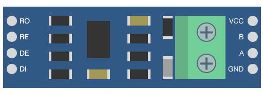
Pin Configuration and Descriptions

The RS485 to TTL Converter typically has the following pinout:

TTL Side (Microcontroller Interface)

Pin Name Description
VCC Power input (3.3V or 5V DC)
GND Ground
TXD Transmit data (TTL level)
RXD Receive data (TTL level)

RS485 Side (Device Interface)

Pin Name Description
A (D+) RS485 differential signal (positive)
B (D-) RS485 differential signal (negative)
GND Ground (optional, for shielding or reference)
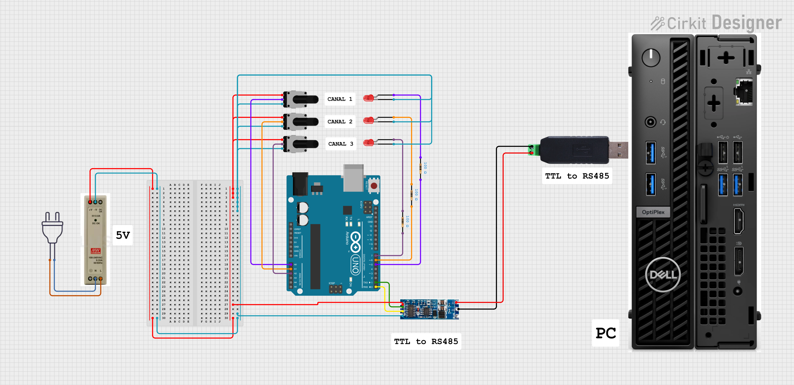
Usage Instructions

How to Use the RS485 to TTL Converter in a Circuit

  1. Power the Converter: Connect the VCC pin to a 3.3V or 5V power source and the GND pin to the ground of your system.
  2. Connect the TTL Side:
    • Connect the TXD pin of the converter to the RX pin of your microcontroller.
    • Connect the RXD pin of the converter to the TX pin of your microcontroller.
  3. Connect the RS485 Side:
    • Connect the A (D+) and B (D-) terminals to the corresponding RS485 device.
    • Optionally, connect the GND terminal for a common ground reference.
  4. Set Up Communication: Configure the baud rate and communication parameters (e.g., parity, stop bits) in your microcontroller code to match the RS485 device.

Important Considerations and Best Practices

  • Ensure that the RS485 bus is properly terminated with a 120-ohm resistor at both ends to prevent signal reflections.
  • Use twisted-pair cables for RS485 connections to minimize noise and interference.
  • Avoid connecting multiple RS485 devices without proper addressing or collision management.
  • Verify that the voltage levels of the TTL side match your microcontroller's logic levels (3.3V or 5V).

Example: Connecting to an Arduino UNO

Below is an example Arduino sketch for using the RS485 to TTL Converter to send and receive data:

// Example: RS485 to TTL Converter with Arduino UNO
// This sketch demonstrates sending and receiving data over RS485

#include <SoftwareSerial.h>

// Define RX and TX pins for SoftwareSerial
#define RX_PIN 10  // Connect to RXD pin of the converter
#define TX_PIN 11  // Connect to TXD pin of the converter

// Create a SoftwareSerial object
SoftwareSerial RS485Serial(RX_PIN, TX_PIN);

void setup() {
  // Start the hardware serial port for debugging
  Serial.begin(9600);
  // Start the RS485 serial communication
  RS485Serial.begin(9600);

  Serial.println("RS485 to TTL Converter Example");
}

void loop() {
  // Send data over RS485
  RS485Serial.println("Hello RS485!");

  // Check if data is available from RS485
  if (RS485Serial.available()) {
    String receivedData = RS485Serial.readString();
    // Print received data to the Serial Monitor
    Serial.print("Received: ");
    Serial.println(receivedData);
  }

  delay(1000); // Wait for 1 second
}

Troubleshooting and FAQs

Common Issues and Solutions

  1. No Communication Between Devices:

    • Verify the wiring connections, especially the A (D+) and B (D-) terminals.
    • Ensure the baud rate and communication settings match on both devices.
  2. Data Corruption or Noise:

    • Check if the RS485 bus is properly terminated with 120-ohm resistors.
    • Use shielded or twisted-pair cables for long-distance communication.
  3. Microcontroller Not Responding:

    • Confirm that the VCC and GND pins are correctly connected.
    • Ensure the TXD and RXD pins are not swapped.
  4. Multiple Devices on RS485 Bus Not Working:

    • Use unique addresses or implement a master-slave protocol to manage communication.
    • Verify that only two termination resistors are present on the bus.

FAQs

Q: Can I use this converter with a 3.3V microcontroller?
A: Yes, the RS485 to TTL Converter is compatible with both 3.3V and 5V logic levels.

Q: What is the maximum communication distance for RS485?
A: RS485 supports communication distances of up to 1200 meters (4000 feet) under ideal conditions.

Q: Do I need to connect the GND pin on the RS485 side?
A: While not always necessary, connecting the GND pin can improve signal integrity, especially in noisy environments.

Q: Can I connect multiple RS485 devices to this converter?
A: Yes, RS485 supports multi-drop communication. Ensure proper addressing and termination for reliable operation.