How to Use RTC: Examples, Pinouts, and Specs
Introduction
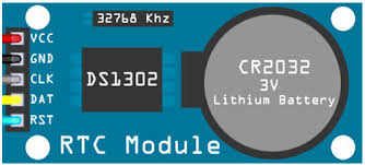
A Real-Time Clock (RTC) module is an electronic component that maintains an accurate track of the current time and date. It continues to run on a battery when the main system power is turned off, ensuring that timekeeping is uninterrupted. RTC modules are commonly used in systems that require time stamps, alarms, or need to perform actions at precise intervals, such as data loggers, digital clocks, and embedded systems.
Explore Projects Built with RTC
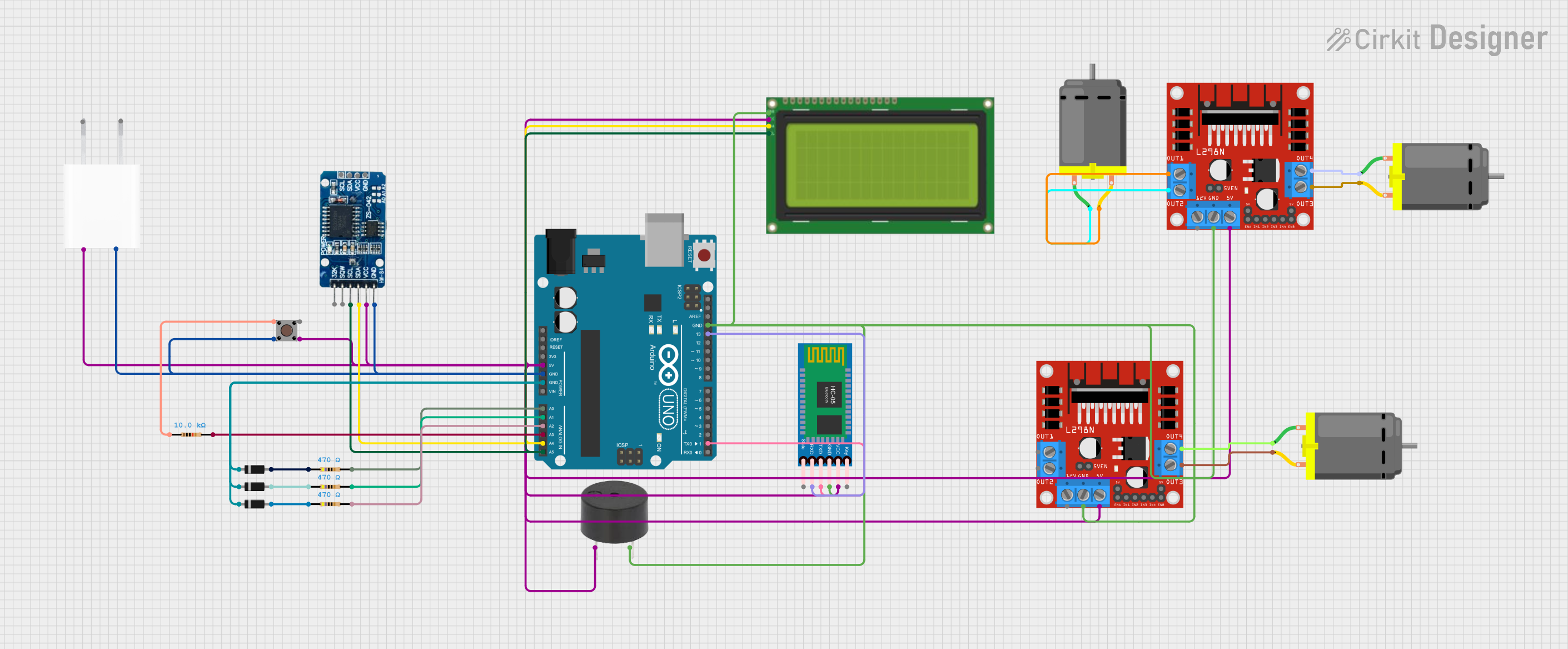
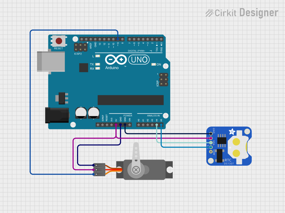

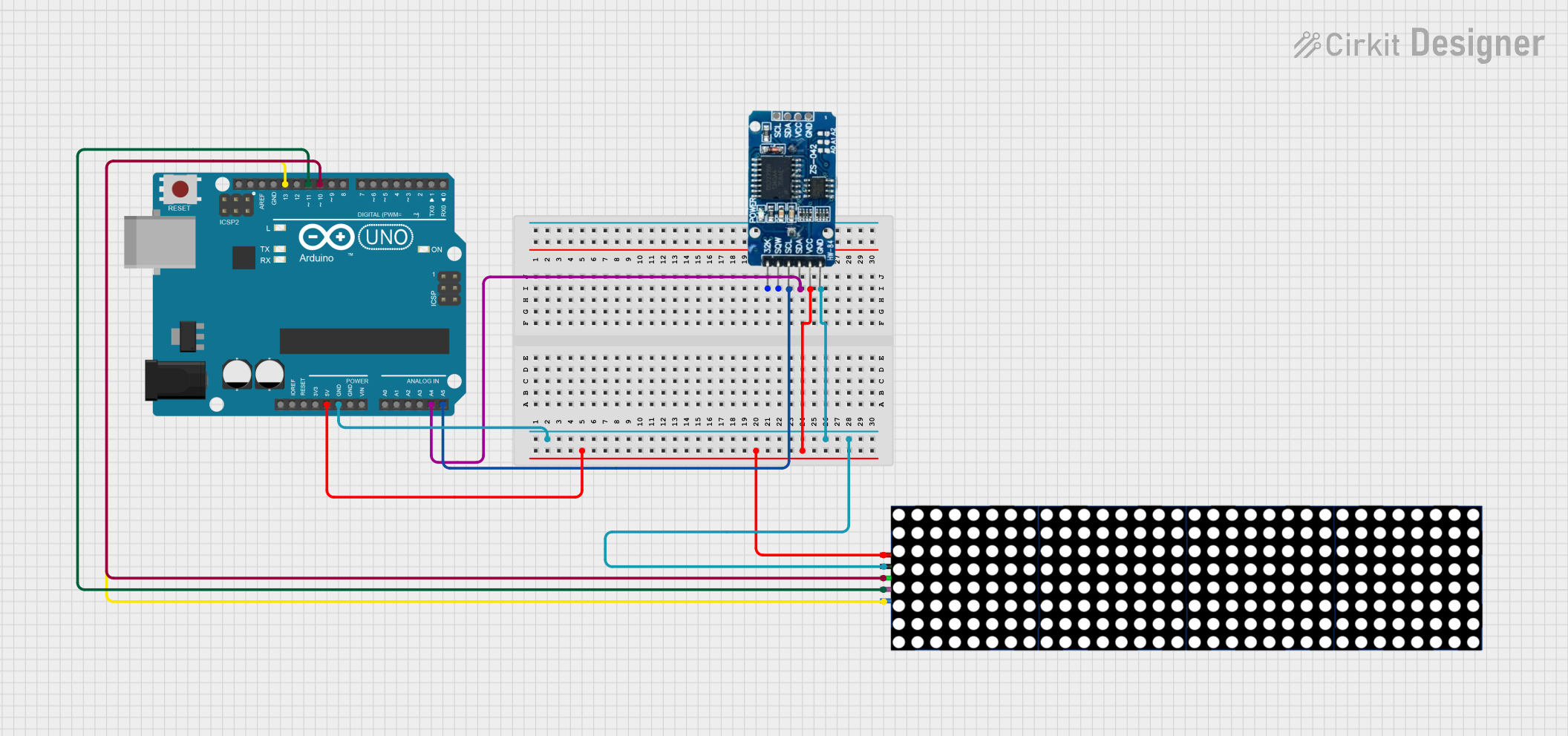
Explore Projects Built with RTC
Common Applications and Use Cases
- Timekeeping in embedded systems
- Timestamping in data logging applications
- Wake-up alarms for microcontroller-based devices
- Maintaining system time in computers and servers
- Time synchronization in network devices
Technical Specifications
Key Technical Details
- Voltage: Typically 2.3V to 5.5V
- Current: Battery current in the range of 1µA to 500µA
- Time Accuracy: ±1 to ±5 ppm at 25°C
- Battery: Coin cell (e.g., CR2032) or supercapacitor for backup power
- Communication Interface: I2C, SPI, or 1-Wire
Pin Configuration and Descriptions
| Pin Number | Name | Description |
|---|---|---|
| 1 | VCC | Power supply input (2.3V to 5.5V) |
| 2 | GND | Ground reference for the module |
| 3 | SDA | Serial Data Line for I2C communication |
| 4 | SCL | Serial Clock Line for I2C communication |
| 5 | SQW | Square Wave/Output Driver (optional) |
| 6 | 32K | 32kHz Output (optional) |
| 7 | RST | Reset pin (optional) |
Usage Instructions
How to Use the RTC in a Circuit
Powering the RTC:
- Connect the VCC pin to a power supply within the specified voltage range.
- Connect the GND pin to the system ground.
Interfacing with a Microcontroller:
- Connect the SDA and SCL pins to the corresponding I2C pins on the microcontroller.
- If available and required, connect the SQW, 32K, and RST pins as needed.
Setting the Time:
- Use the microcontroller to program the current time and date into the RTC module.
Reading the Time:
- Periodically read the time and date from the RTC module using the microcontroller.
Important Considerations and Best Practices
- Ensure that the RTC module's battery is properly installed for timekeeping during power outages.
- Use pull-up resistors on the SDA and SCL lines when interfacing with an I2C bus.
- Avoid placing the RTC module near heat sources to prevent temperature-induced time drift.
- Synchronize the RTC periodically with an accurate time source if high precision is required.
Example Code for Arduino UNO
#include <Wire.h>
#include "RTClib.h"

RTC_DS3231 rtc; // Replace with the specific RTC library and object for your module

void setup() {
  Wire.begin();
  Serial.begin(9600);

  if (!rtc.begin()) {
    Serial.println("Couldn't find RTC");
    while (1);
  }

  if (rtc.lostPower()) {
    Serial.println("RTC lost power, let's set the time!");
    // The following line sets the RTC to the date & time this sketch was compiled
    rtc.adjust(DateTime(F(__DATE__), F(__TIME__)));
  }
}

void loop() {
  DateTime now = rtc.now();

  Serial.print(now.year(), DEC);
  Serial.print('/');
  Serial.print(now.month(), DEC);
  Serial.print('/');
  Serial.print(now.day(), DEC);
  Serial.print(" ");
  Serial.print(now.hour(), DEC);
  Serial.print(':');
  Serial.print(now.minute(), DEC);
  Serial.print(':');
  Serial.print(now.second(), DEC);
  Serial.println();

  delay(1000);
}
Troubleshooting and FAQs
Common Issues Users Might Face
- Time Drift: The RTC may drift over time due to temperature changes or low-quality oscillators.
- Battery Issues: If the RTC time resets after power cycling, the backup battery may be depleted or improperly installed.
- Communication Errors: Ensure proper connection and correct pull-up resistors on the I2C lines.
Solutions and Tips for Troubleshooting
- Time Drift Correction: Regularly synchronize the RTC with a more accurate time source.
- Battery Replacement: Replace the backup battery with a new one, ensuring correct polarity.
- I2C Troubleshooting: Check connections, use a logic analyzer to inspect the I2C signals, and ensure the microcontroller's I2C library is correctly configured.
FAQs
Q: How long will the RTC keep time with the battery? A: It depends on the battery capacity and RTC's power consumption, but typically several years.
Q: Can the RTC module generate interrupts? A: Some RTC modules have an SQW/INT pin that can be programmed to generate interrupts.
Q: Is it necessary to use an external crystal with the RTC module? A: Most RTC modules come with a built-in crystal, but check the datasheet for your specific module.
Q: How do I set the RTC to the correct time? A: You can set the RTC using a microcontroller and RTC library, as shown in the example code.
Q: What should I do if the RTC is not responding to the microcontroller? A: Verify the wiring, check the power supply, ensure the correct I2C address is used, and check for proper pull-up resistors on the I2C lines.