How to Use PWM to Voltage Converter: Examples, Pinouts, and Specs
Introduction
A PWM to Voltage Converter is an electronic circuit designed to transform Pulse Width Modulation (PWM) signals into a corresponding analog voltage level. PWM signals are widely used in digital systems to represent varying levels of power or control, but many devices, such as motors, LEDs, and analog sensors, require a steady analog voltage for operation. This converter bridges the gap by smoothing the PWM signal into a stable DC voltage proportional to the duty cycle of the input signal.
Explore Projects Built with PWM to Voltage Converter
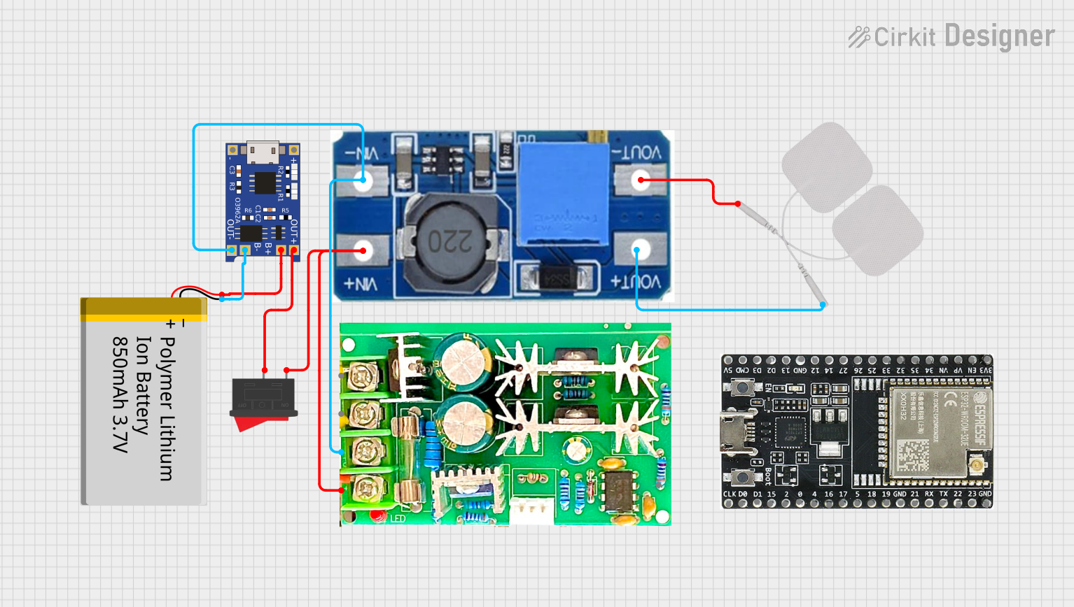
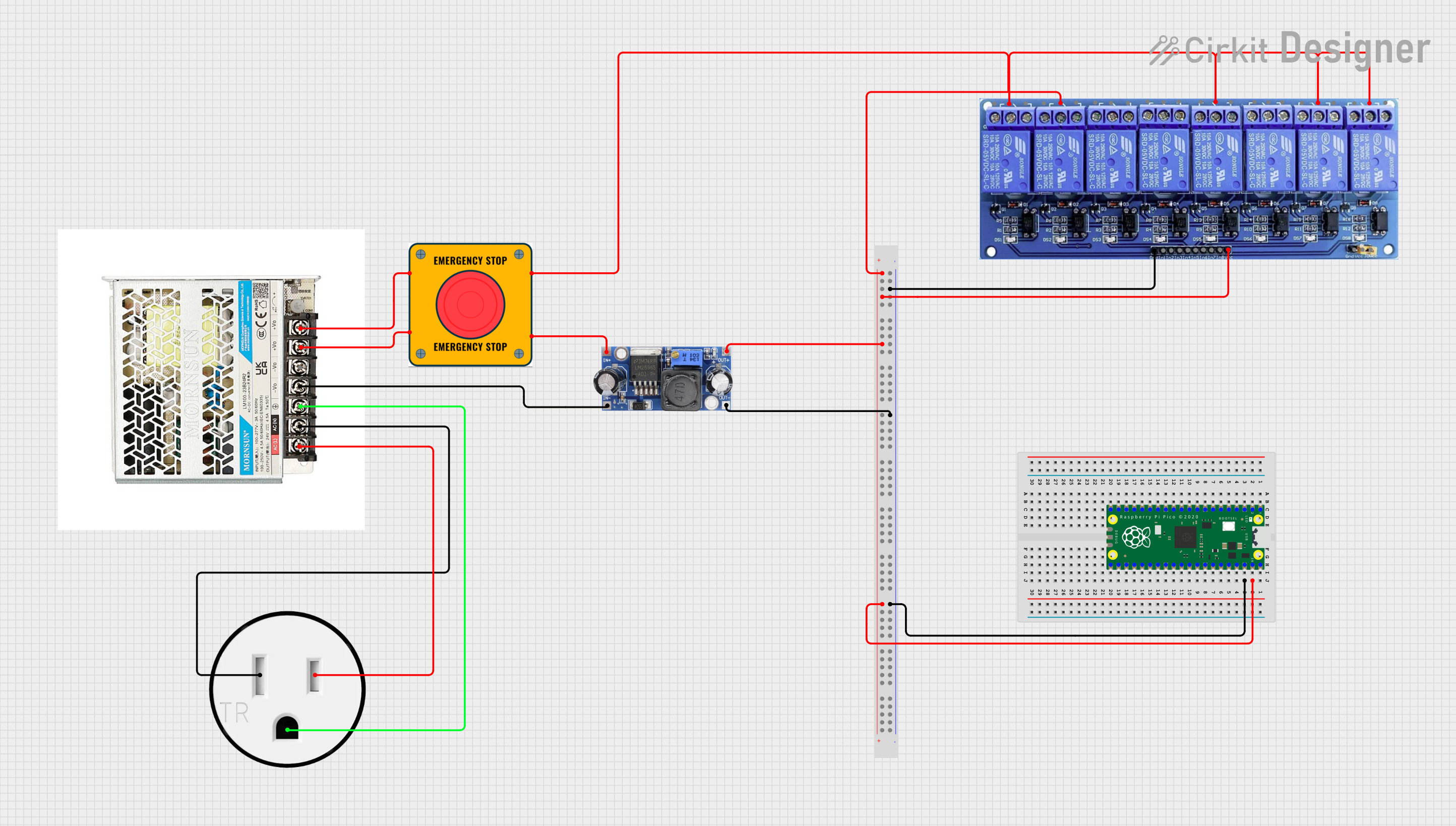

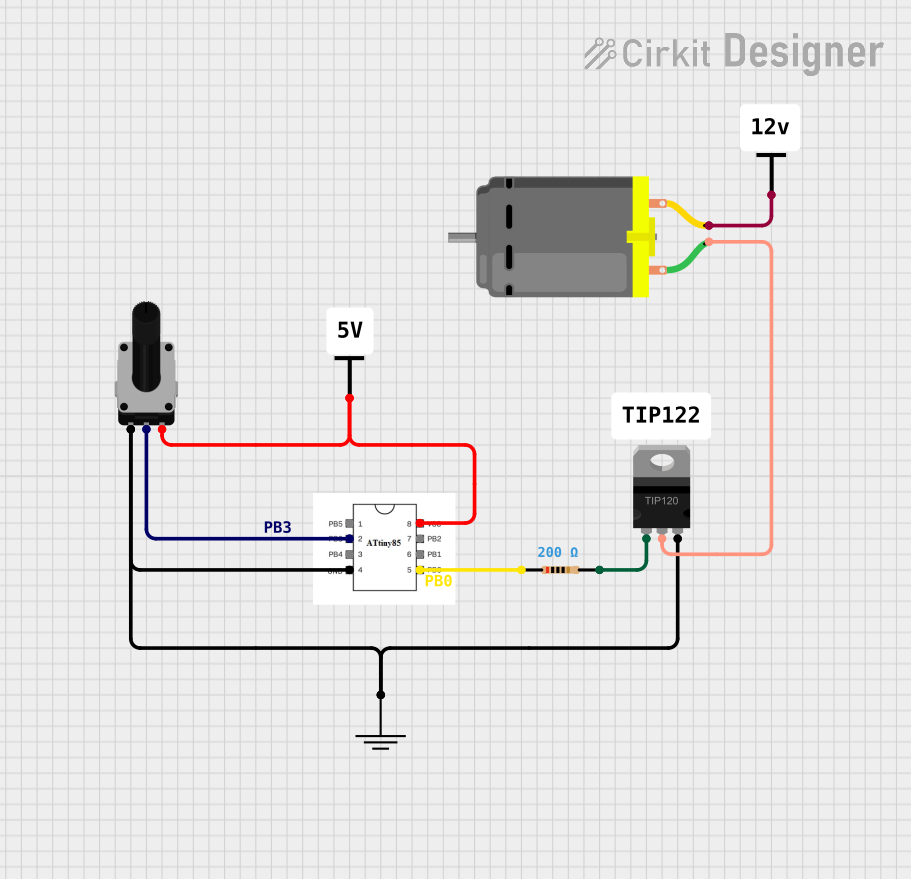
Explore Projects Built with PWM to Voltage Converter
Common Applications and Use Cases
- Motor Speed Control: Converts PWM signals from microcontrollers to analog voltage for motor drivers.
- LED Dimming: Provides smooth brightness control for LEDs.
- Analog Signal Generation: Converts digital PWM signals into analog voltages for use in analog circuits.
- Industrial Automation: Used in systems requiring precise analog control from digital controllers.
- Audio Applications: Converts PWM audio signals into analog waveforms for speakers or amplifiers.
Technical Specifications
Below are the key technical details for a typical PWM to Voltage Converter:
| Parameter | Value |
|---|---|
| Input Voltage Range | 3.3V to 24V |
| Output Voltage Range | 0V to Input Voltage (proportional to duty cycle) |
| Input PWM Frequency | 1 kHz to 10 kHz (typical) |
| Duty Cycle Range | 0% to 100% |
| Output Ripple Voltage | < 10 mV (depends on filter design) |
| Load Current Capacity | Up to 10 mA (typical) |
| Operating Temperature | -40°C to +85°C |
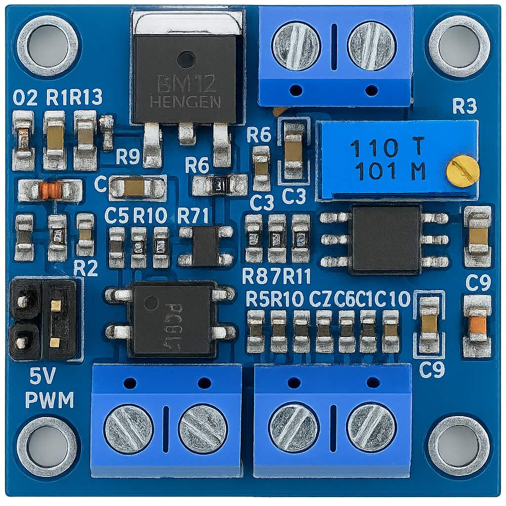
Pin Configuration and Descriptions
The PWM to Voltage Converter typically has the following pin configuration:
| Pin Name | Description |
|---|---|
| VCC | Power supply input (3.3V to 24V, depending on the module). |
| GND | Ground connection. |
| PWM_IN | Input pin for the PWM signal. Accepts a digital PWM signal from a microcontroller. |
| VOUT | Analog voltage output. Provides a DC voltage proportional to the PWM duty cycle. |
Usage Instructions
How to Use the Component in a Circuit
- Power the Converter: Connect the VCC pin to a suitable power supply (e.g., 5V or 12V) and the GND pin to the ground of your circuit.
- Connect the PWM Signal: Attach the PWM_IN pin to the PWM output of your microcontroller or signal generator.
- Obtain the Analog Output: The VOUT pin will provide a DC voltage proportional to the duty cycle of the PWM signal. For example:
- A 50% duty cycle will produce approximately half of the input voltage at VOUT.
- A 100% duty cycle will produce a voltage close to the input voltage at VOUT.
- Filter Design: Ensure the converter has an appropriate low-pass filter (typically an RC filter) to smooth the PWM signal into a stable DC voltage. Most modules include this filter by default.
Important Considerations and Best Practices
- PWM Frequency: Use a PWM frequency within the specified range (1 kHz to 10 kHz). Frequencies too low may result in noticeable ripple, while frequencies too high may not be effectively filtered.
- Load Impedance: Ensure the load connected to the VOUT pin has a sufficiently high impedance to avoid excessive current draw.
- Bypass Capacitors: Add bypass capacitors near the VCC and GND pins to reduce noise and improve stability.
- Calibration: If precise voltage output is required, calibrate the system by adjusting the duty cycle and measuring the output voltage.
Example: Using with Arduino UNO
Below is an example of how to use a PWM to Voltage Converter with an Arduino UNO to generate an analog voltage:
// Example: Generate a PWM signal to control a PWM to Voltage Converter
// Connect the PWM_IN pin of the converter to Arduino pin 9
// The VOUT pin will output a voltage proportional to the duty cycle

const int pwmPin = 9; // PWM output pin

void setup() {
  pinMode(pwmPin, OUTPUT); // Set pin 9 as an output
}

void loop() {
  // Generate a PWM signal with varying duty cycle
  for (int dutyCycle = 0; dutyCycle <= 255; dutyCycle += 5) {
    analogWrite(pwmPin, dutyCycle); // Set PWM duty cycle (0-255)
    delay(100); // Wait 100ms to observe the change in output voltage
  }

  for (int dutyCycle = 255; dutyCycle >= 0; dutyCycle -= 5) {
    analogWrite(pwmPin, dutyCycle); // Decrease PWM duty cycle
    delay(100); // Wait 100ms to observe the change in output voltage
  }
}
Notes:
- The
analogWrite()function generates a PWM signal with an 8-bit resolution (0-255). - The output voltage at the VOUT pin will vary proportionally with the duty cycle.
Troubleshooting and FAQs
Common Issues and Solutions
No Output Voltage at VOUT:
- Cause: PWM signal not connected or incorrect frequency.
- Solution: Verify the PWM_IN connection and ensure the PWM frequency is within the specified range.
High Ripple on Output Voltage:
- Cause: Insufficient filtering of the PWM signal.
- Solution: Check the RC filter design and increase the capacitance or resistance if necessary.
Output Voltage Not Proportional to Duty Cycle:
- Cause: Incorrect power supply voltage or load impedance too low.
- Solution: Ensure the VCC voltage is stable and the load impedance is sufficiently high.
Overheating of the Module:
- Cause: Excessive current draw from the VOUT pin.
- Solution: Reduce the load current or use a buffer circuit to drive high-current loads.
FAQs
Q1: Can I use this converter with a 3.3V microcontroller?
A1: Yes, as long as the VCC voltage is compatible with the converter and the PWM signal amplitude matches the input requirements.
Q2: What happens if the PWM frequency is too low?
A2: A low PWM frequency may result in noticeable ripple on the output voltage. Use a frequency within the recommended range (1 kHz to 10 kHz).
Q3: Can I drive a motor directly with the VOUT pin?
A3: No, the VOUT pin is designed for low-current applications. Use a motor driver or amplifier circuit for high-current loads.
Q4: How do I improve the accuracy of the output voltage?
A4: Use a high-quality low-pass filter and ensure the PWM signal has minimal jitter. Calibration may also help improve accuracy.