
How to Use Adafruit LM73100 Ideal Diode Breakout: Examples, Pinouts, and Specs
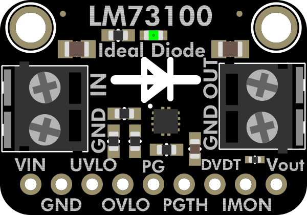
 Design with Adafruit LM73100 Ideal Diode Breakout in Cirkit Designer
Introduction
The Adafruit LM73100 Ideal Diode Breakout (Part ID: 6359) is a compact and efficient breakout board featuring the LM73100 ideal diode controller. This component is designed to minimize voltage drop and power loss in power management applications, making it ideal for efficient power routing and protection. The LM73100 ensures reverse current blocking and provides robust protection against overvoltage and overcurrent conditions.
Explore Projects Built with Adafruit LM73100 Ideal Diode Breakout
 Open Project in Cirkit Designer
 Open Project in Cirkit Designer
 Open Project in Cirkit Designer
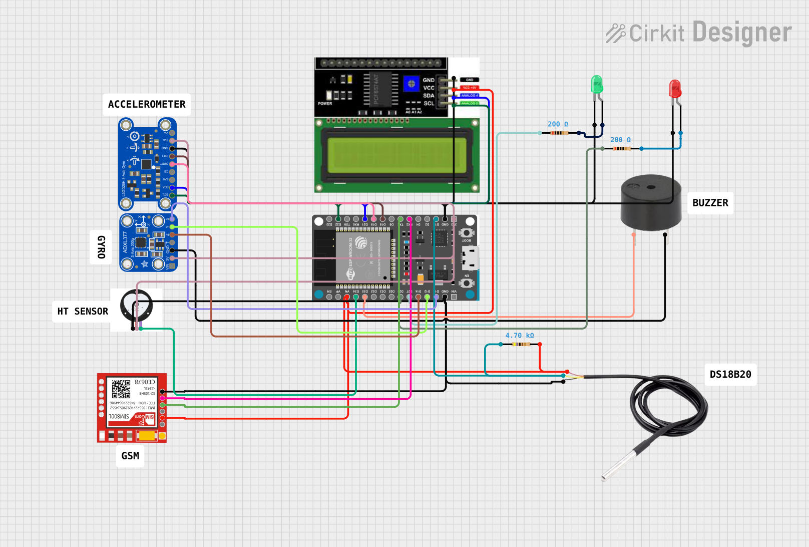 Open Project in Cirkit Designer
Explore Projects Built with Adafruit LM73100 Ideal Diode Breakout
Open Project in Cirkit DesignerOpen Project in Cirkit DesignerOpen Project in Cirkit DesignerOpen Project in Cirkit DesignerCommon Applications and Use Cases
- Power path management in battery-powered devices
- Reverse polarity protection
- Reducing power loss in high-current applications
- Power supply redundancy and OR-ing circuits
- Solar power systems and energy harvesting
Technical Specifications
Key Technical Details
- Input Voltage Range: 2.7V to 42V
- Maximum Continuous Current: Up to 5A (dependent on external MOSFET and thermal conditions)
- Quiescent Current: 0.5mA typical
- Reverse Current Blocking: Yes
- Overvoltage Protection: Adjustable up to 42V
- Undervoltage Lockout (UVLO): Adjustable
- Operating Temperature Range: -40°C to +125°C
- Dimensions: 25mm x 17mm x 4mm (excluding headers)
Pin Configuration and Descriptions
The Adafruit LM73100 Ideal Diode Breakout has the following pinout:
| Pin Name | Type | Description |
|---|---|---|
| VIN | Power Input | Input voltage pin. Connect to the power source (2.7V to 42V). |
| VOUT | Power Output | Output voltage pin. Connect to the load. |
| GND | Ground | Ground connection for the circuit. |
| EN | Digital Input | Enable pin. Pull high to enable the ideal diode; pull low to disable it. |
| OV | Analog Input | Overvoltage adjustment pin. Connect a resistor divider to set the OV threshold. |
| UV | Analog Input | Undervoltage lockout adjustment pin. Connect a resistor divider to set UVLO. |
| FLT | Digital Output | Fault indicator pin. Goes low when a fault condition (e.g., overvoltage) occurs. |
Usage Instructions
How to Use the Component in a Circuit
Power Connections:
- Connect the power source to the
VINpin. - Connect the load to the
VOUTpin. - Ensure the
GNDpin is connected to the ground of the circuit.
- Connect the power source to the
Enable the Ideal Diode:
- Pull the
ENpin high to enable the LM73100. If left floating, the diode may not operate.
- Pull the
Set Overvoltage and Undervoltage Thresholds:
- Use resistor dividers on the
OVandUVpins to set the desired overvoltage and undervoltage thresholds. Refer to the LM73100 datasheet for calculation formulas.
- Use resistor dividers on the
Monitor Faults:
- Connect the
FLTpin to a microcontroller or LED to monitor fault conditions. The pin will go low during a fault.
- Connect the
Thermal Considerations:
- Ensure adequate heat dissipation for the external MOSFET and the breakout board, especially in high-current applications.
Example: Connecting to an Arduino UNO
The Adafruit LM73100 Ideal Diode Breakout can be used with an Arduino UNO to monitor fault conditions and control the enable pin.
Circuit Connections
- Connect
VINto a 12V power source. - Connect
VOUTto the load (e.g., a motor or LED strip). - Connect
GNDto the Arduino GND. - Connect the
ENpin to a digital pin on the Arduino (e.g., D2). - Connect the
FLTpin to another digital pin on the Arduino (e.g., D3).
Arduino Code Example
// Define pin connections
const int enablePin = 2;  // Pin connected to EN
const int faultPin = 3;   // Pin connected to FLT

void setup() {
  pinMode(enablePin, OUTPUT); // Set EN pin as output
  pinMode(faultPin, INPUT);   // Set FLT pin as input

  // Enable the ideal diode
  digitalWrite(enablePin, HIGH);

  // Start serial communication for fault monitoring
  Serial.begin(9600);
}

void loop() {
  // Check the fault pin status
  int faultStatus = digitalRead(faultPin);

  if (faultStatus == LOW) {
    // Fault detected
    Serial.println("Fault detected! Check overvoltage or undervoltage conditions.");
  } else {
    // No fault
    Serial.println("No faults detected. System operating normally.");
  }

  delay(1000); // Wait for 1 second before checking again
}
Important Considerations and Best Practices
- Use appropriately rated external MOSFETs for high-current applications to ensure safe operation.
- Ensure proper resistor divider values for the
OVandUVpins to avoid false triggering. - Add decoupling capacitors near the
VINandVOUTpins to reduce noise and improve stability. - Avoid exceeding the maximum voltage and current ratings to prevent damage to the component.
Troubleshooting and FAQs
Common Issues and Solutions
| Issue | Possible Cause | Solution |
|---|---|---|
No output voltage on VOUT |
EN pin is not pulled high |
Ensure the EN pin is connected to a high logic level or left floating. |
Fault pin (FLT) is always low |
Overvoltage or undervoltage condition is triggered | Verify the resistor divider values on the OV and UV pins. |
| Excessive heat generated by the MOSFET | High current or insufficient heat dissipation | Use a heatsink or a MOSFET with better thermal performance. |
| Output voltage drops under load | Insufficient input voltage or poor connections | Check the input voltage and ensure secure connections to VIN and VOUT. |
FAQs
Can I use this breakout with a 24V power supply?
- Yes, the LM73100 supports input voltages up to 42V. Ensure your load and external components are rated for 24V operation.
What happens if the input voltage drops below the UVLO threshold?
- The LM73100 will disable the output to protect the load from undervoltage conditions.
Can I use this breakout for reverse polarity protection?
- Yes, the LM73100 provides reverse current blocking, making it suitable for reverse polarity protection.
How do I adjust the overvoltage and undervoltage thresholds?
- Use resistor dividers on the
OVandUVpins. Refer to the LM73100 datasheet for detailed calculations.
- Use resistor dividers on the
By following this documentation, you can effectively integrate the Adafruit LM73100 Ideal Diode Breakout into your power management applications.