
How to Use MCP3008: Examples, Pinouts, and Specs
 Design with MCP3008 in Cirkit Designer
Introduction
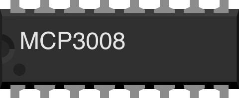
The MCP3008, manufactured by Microchip Technology, is an 8-channel, 10-bit analog-to-digital converter (ADC). It is designed to convert analog signals into digital data, making it an essential component for interfacing sensors and other analog devices with digital systems. The MCP3008 communicates via the Serial Peripheral Interface (SPI), ensuring fast and reliable data transfer. Its compact design and versatility make it ideal for applications such as sensor data acquisition, IoT devices, and embedded systems.
Explore Projects Built with MCP3008
 Open Project in Cirkit Designer
 Open Project in Cirkit Designer
 Open Project in Cirkit Designer
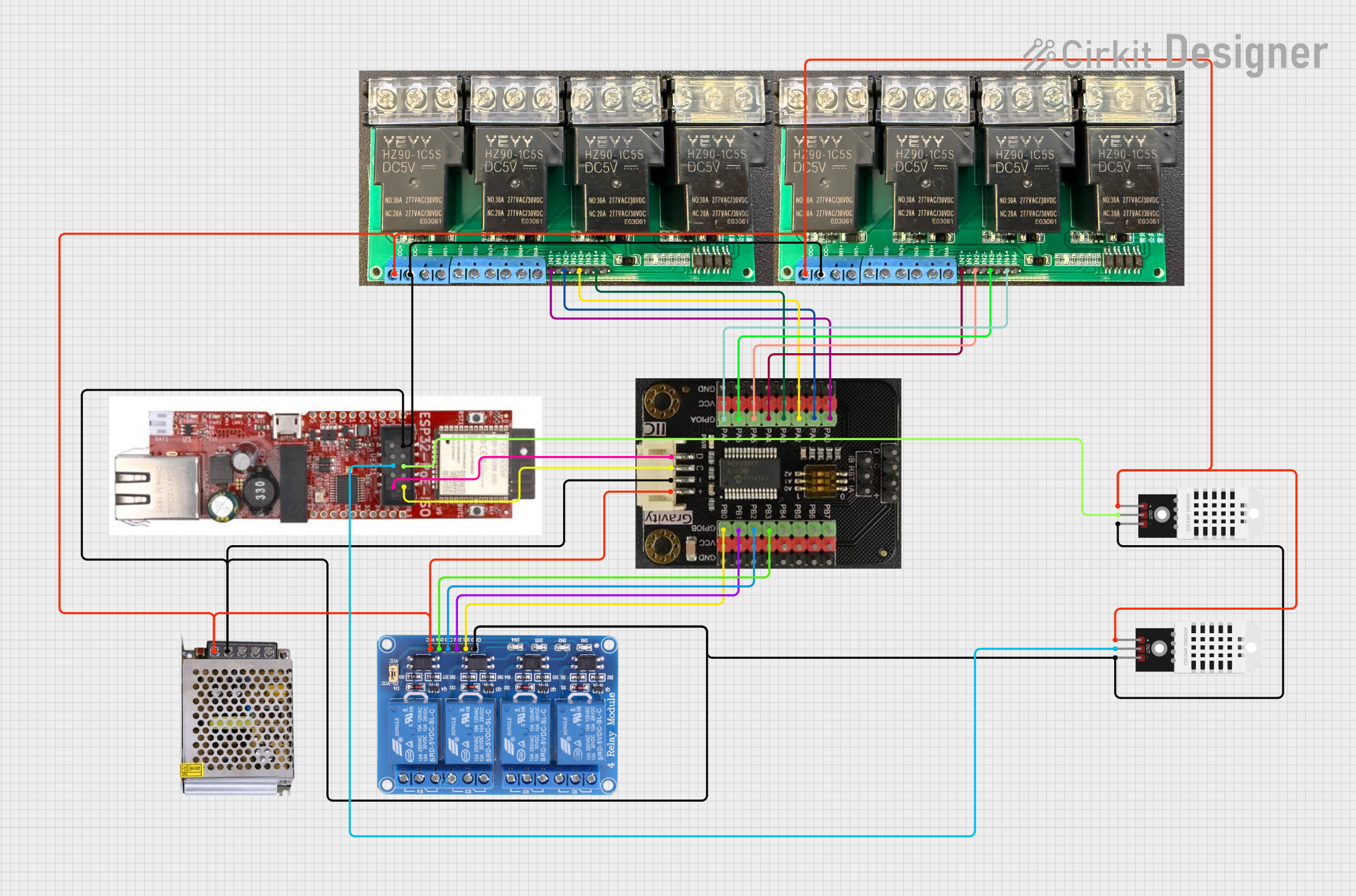 Open Project in Cirkit Designer
Explore Projects Built with MCP3008
Open Project in Cirkit DesignerOpen Project in Cirkit DesignerOpen Project in Cirkit DesignerOpen Project in Cirkit DesignerCommon Applications
- Sensor interfacing (e.g., temperature, light, and pressure sensors)
- Data acquisition systems
- IoT devices and smart home applications
- Robotics and automation
- Audio signal processing
Technical Specifications
The MCP3008 is a high-performance ADC with the following key specifications:
| Parameter | Value |
|---|---|
| Resolution | 10 bits |
| Number of Channels | 8 (single-ended) or 4 (differential) |
| Input Voltage Range | 0V to VREF |
| Reference Voltage (VREF) | 2.7V to 5.5V |
| Supply Voltage (VDD) | 2.7V to 5.5V |
| Communication Interface | SPI (Serial Peripheral Interface) |
| Maximum Sampling Rate | 200 ksps (at 5V) |
| Operating Temperature Range | -40°C to +85°C |
| Package Options | PDIP, SOIC, TSSOP |
Pin Configuration and Descriptions
The MCP3008 has 16 pins, with the following configuration:
| Pin Number | Pin Name | Description |
|---|---|---|
| 1 | CH0 | Analog input channel 0 |
| 2 | CH1 | Analog input channel 1 |
| 3 | CH2 | Analog input channel 2 |
| 4 | CH3 | Analog input channel 3 |
| 5 | CH4 | Analog input channel 4 |
| 6 | CH5 | Analog input channel 5 |
| 7 | CH6 | Analog input channel 6 |
| 8 | CH7 | Analog input channel 7 |
| 9 | DGND | Digital ground |
| 10 | CS/SHDN | Chip select/shutdown control |
| 11 | DIN | SPI data input (MOSI) |
| 12 | DOUT | SPI data output (MISO) |
| 13 | CLK | SPI clock input |
| 14 | AGND | Analog ground |
| 15 | VREF | Reference voltage input |
| 16 | VDD | Positive supply voltage |
Usage Instructions
How to Use the MCP3008 in a Circuit
- Power Supply: Connect the VDD pin to a 3.3V or 5V power source, depending on your system. Connect the AGND and DGND pins to ground.
- Reference Voltage: Provide a stable reference voltage to the VREF pin. This determines the ADC's input range (e.g., 0V to 5V if VREF = 5V).
- SPI Connections:
- Connect the
CS/SHDNpin to a GPIO pin on your microcontroller to enable/disable the chip. - Connect the
DINpin to the SPI MOSI line. - Connect the
DOUTpin to the SPI MISO line. - Connect the
CLKpin to the SPI clock line.
- Connect the
- Analog Inputs: Connect your analog signals to the CH0–CH7 pins. Ensure the input voltage does not exceed the reference voltage.
- SPI Configuration: Configure your microcontroller's SPI interface to communicate with the MCP3008. Use SPI mode 0 (CPOL = 0, CPHA = 0).
Example: Interfacing MCP3008 with Arduino UNO
Below is an example of how to read an analog signal from channel 0 of the MCP3008 using an Arduino UNO:
#include <SPI.h>

// Define MCP3008 connections
const int CS_PIN = 10; // Chip Select pin connected to Arduino pin 10

void setup() {
  Serial.begin(9600); // Initialize serial communication
  SPI.begin();        // Initialize SPI communication
  pinMode(CS_PIN, OUTPUT); // Set CS pin as output
  digitalWrite(CS_PIN, HIGH); // Set CS pin to HIGH (inactive)
}

int readMCP3008(int channel) {
  // Ensure the channel is valid (0-7)
  if (channel < 0 || channel > 7) return -1;

  digitalWrite(CS_PIN, LOW); // Activate the MCP3008 by setting CS LOW

  // Send start bit, single-ended mode, and channel selection
  byte command = 0b00000001; // Start bit
  byte config = (0b1000 | channel) << 4; // Single-ended mode + channel
  SPI.transfer(command); // Send start bit
  byte highByte = SPI.transfer(config); // Send config and receive high byte
  byte lowByte = SPI.transfer(0x00); // Receive low byte

  digitalWrite(CS_PIN, HIGH); // Deactivate the MCP3008 by setting CS HIGH

  // Combine high and low bytes into a 10-bit result
  int result = ((highByte & 0x03) << 8) | lowByte;
  return result;
}

void loop() {
  int value = readMCP3008(0); // Read from channel 0
  Serial.print("Channel 0 Value: ");
  Serial.println(value); // Print the ADC value
  delay(500); // Wait for 500ms
}
Important Considerations
- Input Voltage Range: Ensure the analog input voltage does not exceed the reference voltage to avoid damage.
- Noise Reduction: Use decoupling capacitors near the power supply pins to reduce noise.
- SPI Speed: The SPI clock frequency should not exceed 3.6 MHz at 5V or 1.8 MHz at 2.7V.
Troubleshooting and FAQs
Common Issues
- Incorrect Readings:
- Ensure the reference voltage is stable and matches the expected range.
- Verify that the SPI connections are correct and secure.
- No Output Data:
- Check if the
CS/SHDNpin is being toggled correctly. - Ensure the SPI mode is set to mode 0 (CPOL = 0, CPHA = 0).
- Check if the
- Noise in Readings:
- Use proper grounding and shielding techniques.
- Add a low-pass filter to the analog input if necessary.
FAQs
Q: Can the MCP3008 handle negative input voltages?
A: No, the MCP3008 cannot handle negative voltages. The input voltage range is 0V to VREF.
Q: What happens if the input voltage exceeds VREF?
A: Exceeding VREF can result in inaccurate readings and may damage the device.
Q: Can I use the MCP3008 with a 3.3V system?
A: Yes, the MCP3008 operates with supply voltages as low as 2.7V, making it compatible with 3.3V systems.
Q: How do I use differential mode?
A: In differential mode, pair the input channels (e.g., CH0 and CH1) to measure the voltage difference between them. Refer to the datasheet for configuration details.