How to Use Sound Sensor: Examples, Pinouts, and Specs
Introduction
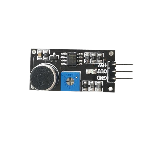
A sound sensor is an electronic device designed to detect sound levels in the environment and convert them into electrical signals. These sensors are commonly used in various applications such as noise level monitoring, security systems, and interactive projects that respond to voice commands or environmental sounds. They are particularly popular in hobbyist projects with microcontrollers like the Arduino UNO.
Explore Projects Built with Sound Sensor
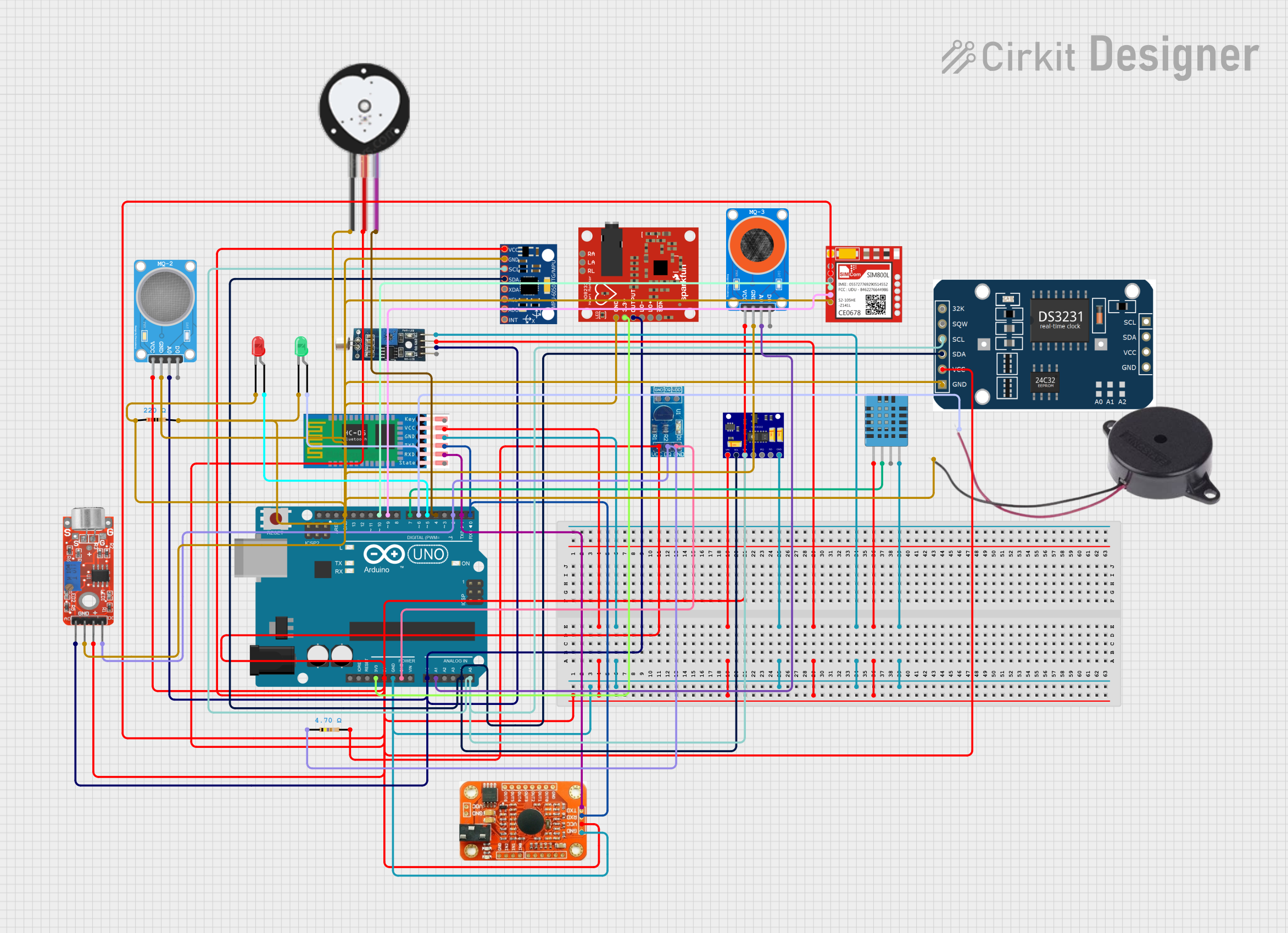
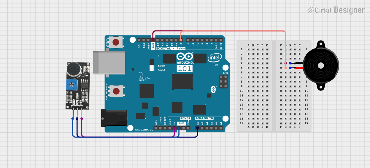
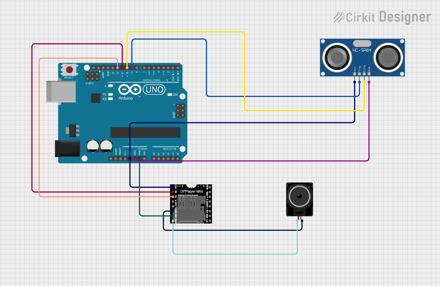
Explore Projects Built with Sound Sensor
Technical Specifications
Key Technical Details
- Operating Voltage: Typically 3.3V to 5V
- Current Consumption: Varies with model, often in the range of 4-30 mA
- Frequency Range: Generally sensitive to frequencies in the range of human hearing (20 Hz to 20 kHz)
- Output: Analog voltage corresponding to sound level; some models may include a digital output that triggers at a certain sound level
Pin Configuration and Descriptions
| Pin Name | Description |
|---|---|
| VCC | Connect to 3.3V or 5V power supply |
| GND | Connect to ground |
| A0 | Analog output, provides a voltage signal representing sound intensity |
| D0 | Digital output, goes high when sound intensity exceeds a certain threshold |
Usage Instructions
Integrating with a Circuit
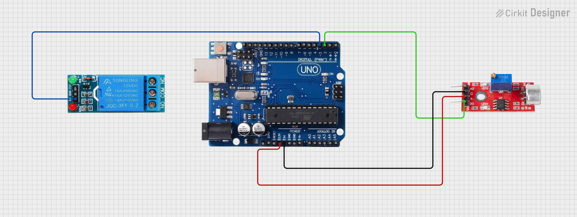
- Power Connections: Connect the VCC pin to the 5V output on the Arduino and the GND pin to one of the Arduino's ground pins.
- Signal Connections: Connect the A0 pin to one of the Arduino's analog input pins if you wish to measure the level of sound. If you want to use the digital output, connect the D0 pin to one of the Arduino's digital input pins.
- Adjusting Sensitivity: Some sound sensors have a potentiometer to adjust the sensitivity of the digital output threshold. Turn this potentiometer to calibrate the sensor for your specific application.
Best Practices
- Avoid Noise: Place the sensor away from noisy components such as motors or high-frequency electronics that may interfere with sound detection.
- Calibration: Calibrate the sensor in the environment where it will be used to ensure accurate readings.
- Shielding: Use appropriate shielding to protect the sensor from wind or other environmental factors that may affect readings.
Example Code for Arduino UNO
// Define the pin connected to the sound sensor's analog output
const int soundSensorPin = A0;

void setup() {
  // Initialize serial communication at 9600 bits per second:
  Serial.begin(9600);
}

void loop() {
  // Read the value from the sound sensor:
  int sensorValue = analogRead(soundSensorPin);
  // Print out the value to the serial monitor
  Serial.println(sensorValue);
  delay(1); // Delay in between reads for stability
}
Troubleshooting and FAQs
Common Issues
- Inconsistent Readings: Ensure that the sensor is not being affected by external vibrations or airflow. Check for loose connections.
- No Output: Verify that the sensor is correctly powered and that the pins are connected to the correct Arduino pins.
- Too Sensitive/Not Sensitive Enough: Adjust the sensitivity potentiometer on the sensor.
FAQs
Q: Can the sound sensor differentiate between different sounds or frequencies? A: Basic sound sensors output an analog signal corresponding to the overall intensity of the sound, not specific frequencies or sounds.
Q: How can I use the digital output?
A: The digital output can be used as a simple sound detection switch that triggers when the sound level exceeds a certain threshold. Connect it to a digital pin and use digitalRead() in your code to detect the state change.
Q: What is the range of sound levels the sensor can detect? A: This varies by model, but most sensors are designed to detect sounds within the range of human hearing. Check the datasheet for your specific model for precise figures.
Q: How do I reduce false triggers from ambient noise? A: Increase the threshold level using the onboard potentiometer, or implement software filtering techniques to distinguish between ambient noise and actual sound events of interest.