Cirkit Designer
Your all-in-one circuit design IDE
Home /
Component Documentation
How to Use KY-004 Key Switch Module: Examples, Pinouts, and Specs
Introduction
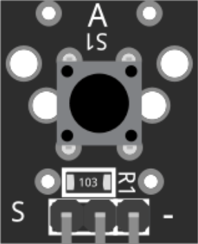
The KY-004 Key Switch Module is a small, versatile component designed for detecting button presses in various electronic projects. It features a push-button switch that outputs a digital signal when pressed, making it an ideal choice for simple user input in microcontroller-based systems. This module is commonly used in DIY electronics, prototyping, and educational projects due to its ease of use and reliability.
Explore Projects Built with KY-004 Key Switch Module
Arduino UNO Controlled GSM Interface with LCD Feedback and Relay Switching
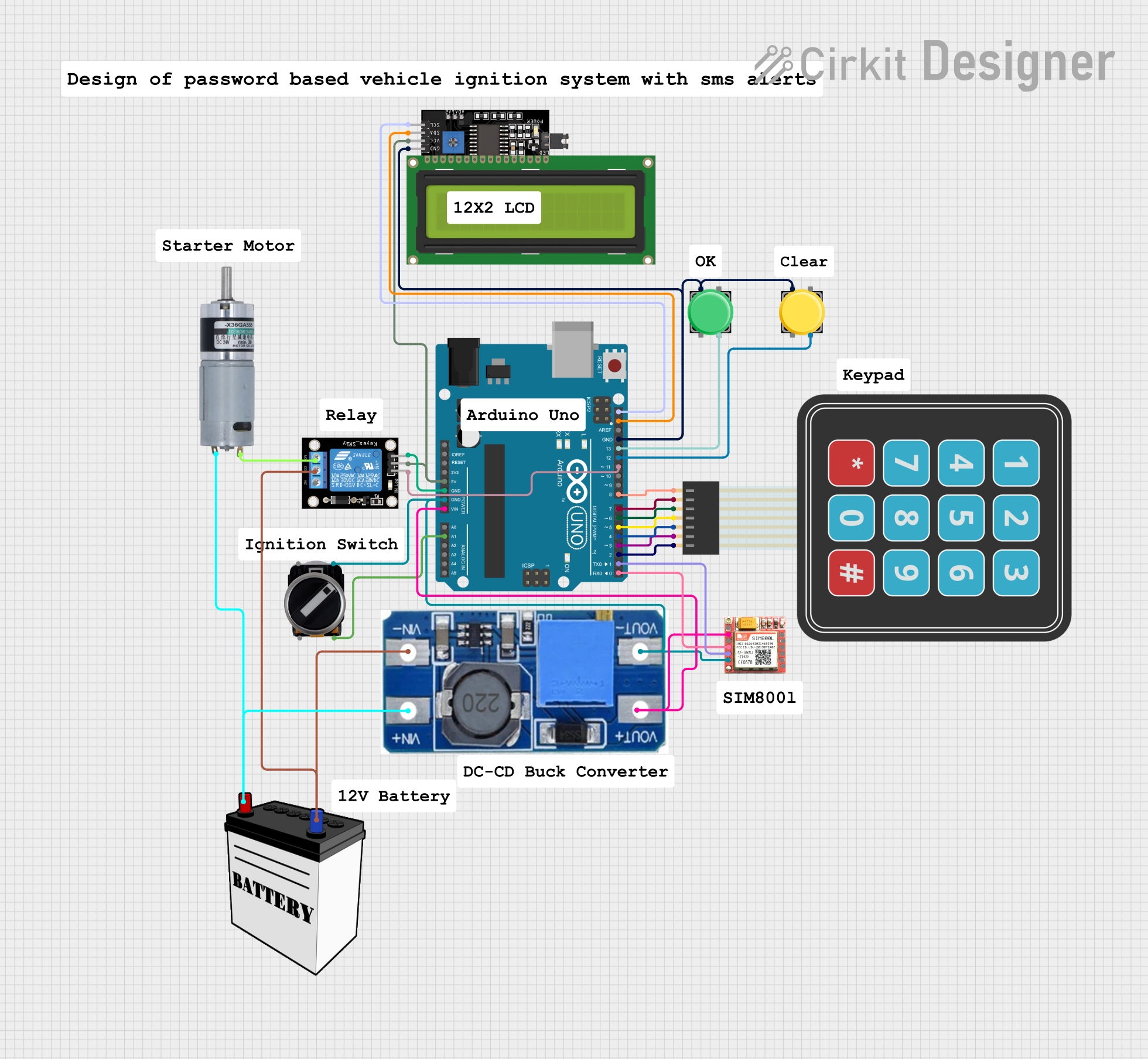
This circuit features an Arduino UNO microcontroller interfaced with a variety of components. It controls a KY-019 relay module to switch power to a motor and communicates with a SIM800L module for cellular connectivity. User inputs are handled via a membrane matrix keypad and pushbuttons, and feedback is provided through an I2C-connected LCD display. A step-up boost converter adjusts voltage from a 12V battery to power the motor, and a 3-position switch is used for additional control.
Arduino Nano Joystick-Controlled Bluetooth Module with Battery Power

This circuit is a wireless joystick controller that uses an Arduino Nano to read analog signals from a KY-023 Dual Axis Joystick Module and transmits the data via an HC-05 Bluetooth Module. The system is powered by a 18650 Li-Ion battery with a rocker switch for power control.
Arduino UNO-Based Smart Humidifier and Temperature Monitor with OLED Display
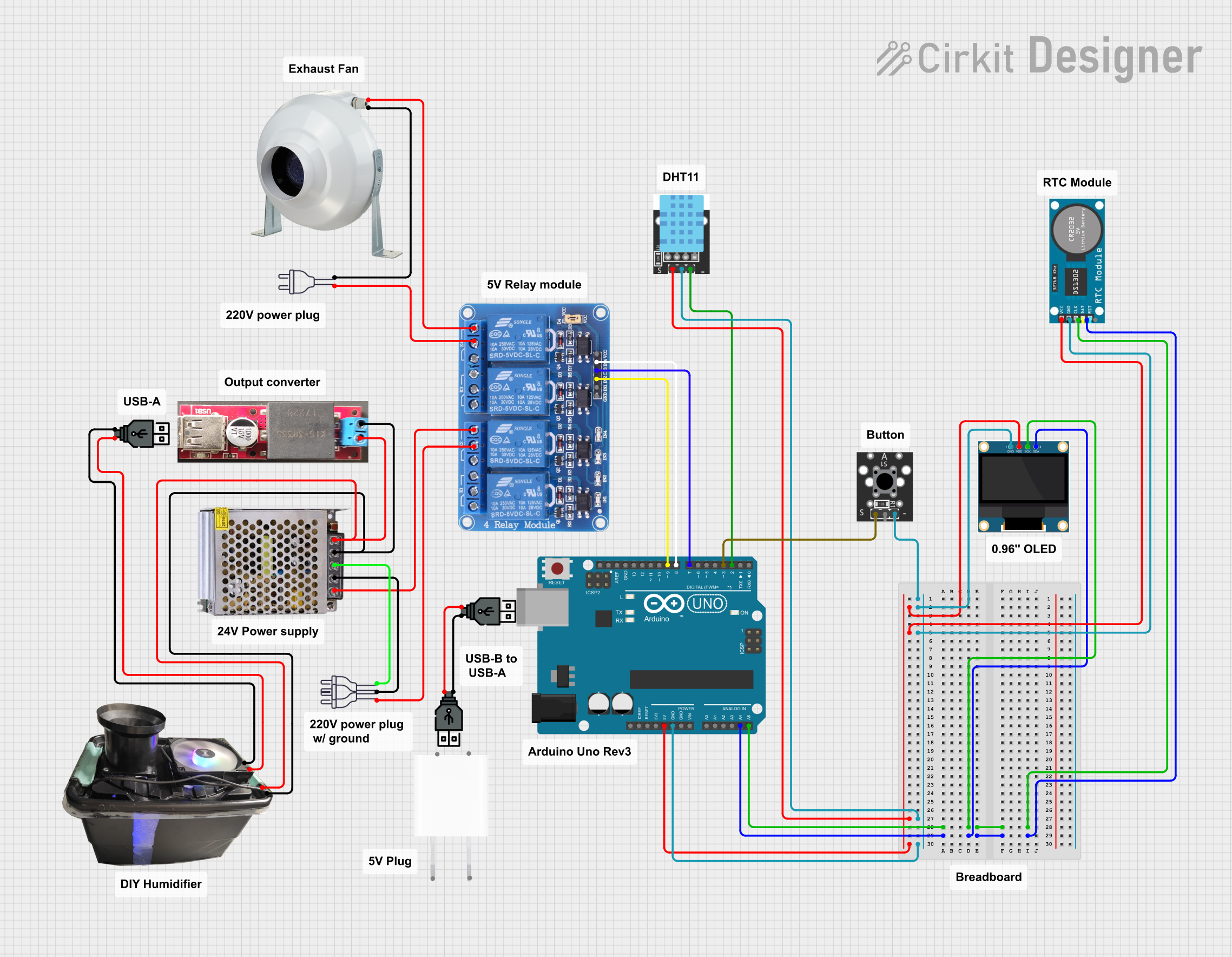
This circuit is a smart environmental monitoring and control system. It uses an Arduino UNO to read data from a temperature-humidity sensor and a real-time clock, displays information on an OLED screen, and controls an exhaust fan and a humidifier via a relay module. The system is powered by a 5V power supply and includes a key switch for user input.
Wireless Joystick-Controlled Interface with Arduino Nano and NRF24L01

This circuit features an Arduino Nano interfaced with a KY-023 Dual Axis Joystick Module for analog input, and an NRF24L01 module for wireless communication. The joystick provides x and y-axis control signals to the Arduino's analog inputs and a switch signal to a digital input, while the NRF24L01 enables the Arduino to communicate with other devices wirelessly. The 2x 18650 batteries supply power to the Arduino, which in turn powers the joystick and the NRF24L01 module.
Explore Projects Built with KY-004 Key Switch Module
Arduino UNO Controlled GSM Interface with LCD Feedback and Relay Switching
This circuit features an Arduino UNO microcontroller interfaced with a variety of components. It controls a KY-019 relay module to switch power to a motor and communicates with a SIM800L module for cellular connectivity. User inputs are handled via a membrane matrix keypad and pushbuttons, and feedback is provided through an I2C-connected LCD display. A step-up boost converter adjusts voltage from a 12V battery to power the motor, and a 3-position switch is used for additional control.
Arduino Nano Joystick-Controlled Bluetooth Module with Battery Power
This circuit is a wireless joystick controller that uses an Arduino Nano to read analog signals from a KY-023 Dual Axis Joystick Module and transmits the data via an HC-05 Bluetooth Module. The system is powered by a 18650 Li-Ion battery with a rocker switch for power control.
Arduino UNO-Based Smart Humidifier and Temperature Monitor with OLED Display
This circuit is a smart environmental monitoring and control system. It uses an Arduino UNO to read data from a temperature-humidity sensor and a real-time clock, displays information on an OLED screen, and controls an exhaust fan and a humidifier via a relay module. The system is powered by a 5V power supply and includes a key switch for user input.
Wireless Joystick-Controlled Interface with Arduino Nano and NRF24L01
This circuit features an Arduino Nano interfaced with a KY-023 Dual Axis Joystick Module for analog input, and an NRF24L01 module for wireless communication. The joystick provides x and y-axis control signals to the Arduino's analog inputs and a switch signal to a digital input, while the NRF24L01 enables the Arduino to communicate with other devices wirelessly. The 2x 18650 batteries supply power to the Arduino, which in turn powers the joystick and the NRF24L01 module.
Common Applications and Use Cases
- User Input: Ideal for projects requiring a simple button press input.
- Prototyping: Useful in breadboard setups for testing and development.
- Educational Projects: Great for teaching basic electronics and microcontroller interfacing.
- Interactive Devices: Can be used in interactive installations and devices requiring user interaction.
Technical Specifications
Key Technical Details
| Parameter | Value |
|---|---|
| Operating Voltage | 3.3V to 5V |
| Output Type | Digital |
| Dimensions | 18.5mm x 15mm x 7mm |
| Button Type | Momentary push-button |
| Pin Count | 3 |
Pin Configuration and Descriptions
| Pin Number | Pin Name | Description |
|---|---|---|
| 1 | S | Signal output (digital) |
| 2 | Middle | Not connected (NC) |
| 3 | - | Ground (GND) |
Usage Instructions
How to Use the Component in a Circuit
Connect the Pins:
- Connect the
Spin to a digital input pin on your microcontroller (e.g., Arduino). - Connect the
-pin to the ground (GND) of your microcontroller. - The middle pin is not connected and can be left unconnected.
- Connect the
Power the Module:
- Ensure the module is powered with a voltage between 3.3V and 5V, which is typically provided by the microcontroller.
Read the Button State:
- When the button is pressed, the
Spin outputs a digital HIGH signal. - When the button is not pressed, the
Spin outputs a digital LOW signal.
- When the button is pressed, the
Important Considerations and Best Practices
- Debouncing: Mechanical switches like the KY-004 can produce noise or "bounce" when pressed. Implement software debouncing in your code to ensure reliable button press detection.
- Pull-down Resistor: If your microcontroller does not have internal pull-down resistors, consider adding an external pull-down resistor (e.g., 10kΩ) between the
Spin and GND to ensure a stable LOW signal when the button is not pressed.
Example Code for Arduino UNO
// KY-004 Key Switch Module Example Code for Arduino UNO

const int buttonPin = 2;  // Pin connected to the S pin of KY-004
const int ledPin = 13;    // Pin connected to the onboard LED

void setup() {
  pinMode(buttonPin, INPUT);  // Set button pin as input
  pinMode(ledPin, OUTPUT);    // Set LED pin as output
  Serial.begin(9600);         // Initialize serial communication
}

void loop() {
  int buttonState = digitalRead(buttonPin);  // Read the button state

  if (buttonState == HIGH) {  // If button is pressed
    digitalWrite(ledPin, HIGH);  // Turn on the LED
    Serial.println("Button Pressed");  // Print message to serial monitor
  } else {
    digitalWrite(ledPin, LOW);  // Turn off the LED
  }

  delay(50);  // Small delay for debouncing
}
Troubleshooting and FAQs
Common Issues Users Might Face
Button Not Responding:
- Solution: Check the wiring connections. Ensure the
Spin is connected to the correct digital input pin on the microcontroller and the-pin is connected to GND.
- Solution: Check the wiring connections. Ensure the
Unstable Button Press Detection:
- Solution: Implement software debouncing in your code to filter out noise and ensure reliable detection of button presses.
No Output Signal:
- Solution: Verify the operating voltage is within the specified range (3.3V to 5V). Check for any loose connections or damaged components.
Solutions and Tips for Troubleshooting
- Check Connections: Ensure all connections are secure and correctly oriented.
- Use Serial Monitor: Utilize the serial monitor to print debug messages and verify the button state.
- Test with Multimeter: Use a multimeter to check the voltage levels at the
Spin when the button is pressed and not pressed.
By following this documentation, users can effectively integrate the KY-004 Key Switch Module into their projects, ensuring reliable and accurate button press detection.