How to Use NANO Shield Board W/ Power Switch: Examples, Pinouts, and Specs
Introduction
The NANO Shield Board with Power Switch is an accessory designed to enhance the functionality of the Arduino Nano microcontroller. It provides a convenient way to connect various modules and sensors to the Arduino Nano while allowing for easy power management through an onboard power switch. This shield is ideal for hobbyists, educators, and prototyping professionals who require a compact and versatile platform for their projects.
Explore Projects Built with NANO Shield Board W/ Power Switch

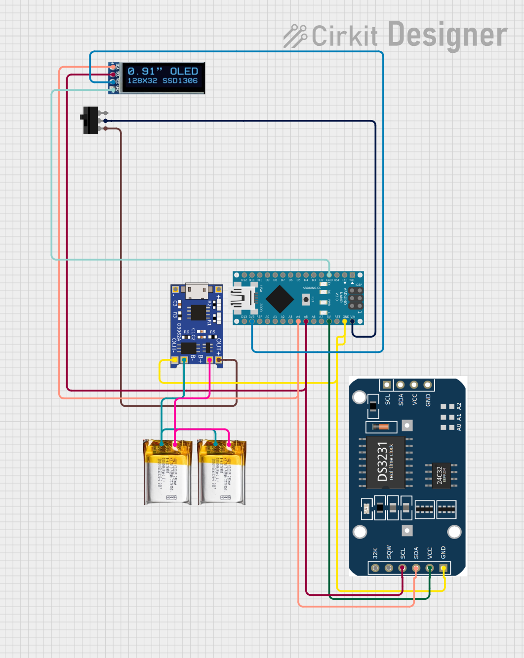
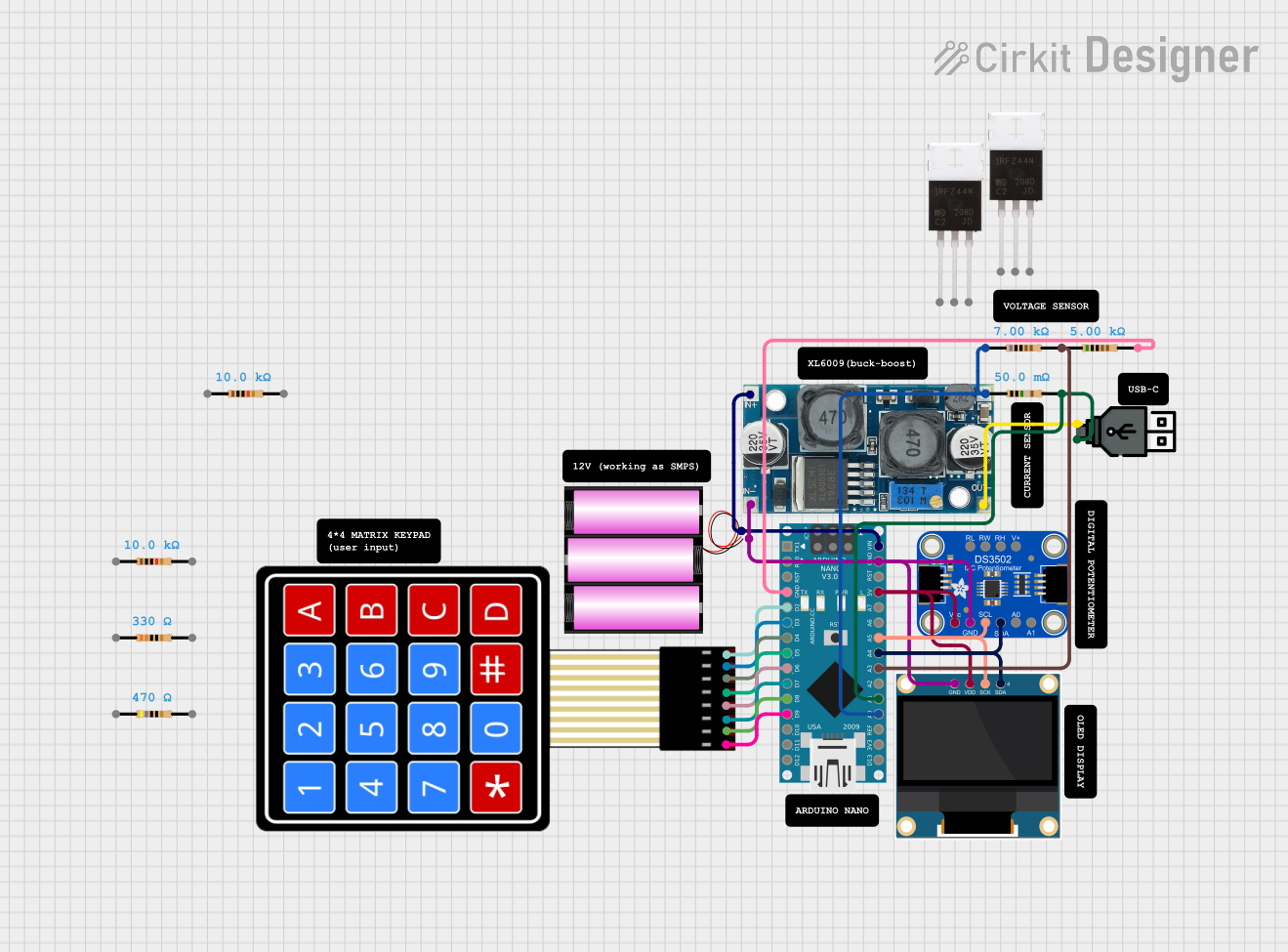
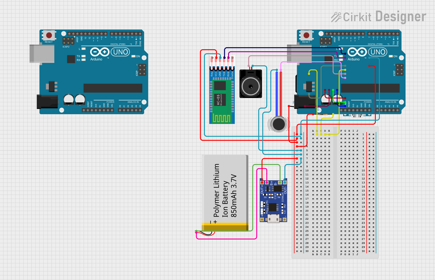
Explore Projects Built with NANO Shield Board W/ Power Switch
Common Applications and Use Cases
- Prototyping electronic circuits
- Educational projects and learning platforms
- Robotics and automation systems
- DIY electronics and maker projects
- IoT (Internet of Things) devices
Technical Specifications
Key Technical Details
- Compatible Microcontroller: Arduino Nano
- Operating Voltage: Typically 5V (supplied by the Arduino Nano)
- Power Switch: Onboard switch for easy power control
- Expansion Ports: Multiple I/O pins for connecting sensors and modules
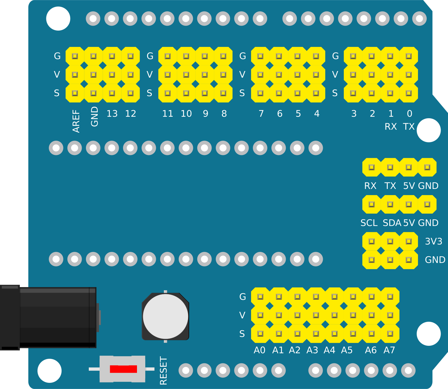
Pin Configuration and Descriptions
| Pin Number | Description | Notes |
|---|---|---|
| 1 | +5V | Power supply from Arduino Nano |
| 2 | GND | Ground connection |
| 3 | Analog Pins (A0-A7) | Analog input pins |
| 4 | Digital Pins (D2-D13) | Digital I/O pins |
| 5 | I2C Pins (A4/A5 or SDA/SCL) | For I2C communication |
| 6 | SPI Pins (D10-D13) | For SPI communication |
| 7 | UART Pins (D0/D1 or RX/TX) | For serial communication |
| 8 | Reset | Resets the Arduino Nano |
| 9 | Power Switch | Controls power to the shield |
Usage Instructions
How to Use the Component in a Circuit
Mounting the Arduino Nano:
- Carefully align the pins of the Arduino Nano with the female headers on the shield board.
- Gently press the Arduino Nano down to ensure a secure and proper connection.
Powering the Shield:
- Use the onboard power switch to turn on the shield, which will also power the Arduino Nano.
- Ensure that the power source connected to the Arduino Nano is within the recommended voltage range.
Connecting Modules and Sensors:
- Utilize the expansion ports to connect various modules and sensors to the corresponding I/O pins.
- Pay attention to the voltage and current requirements of the connected peripherals to avoid damage.
Important Considerations and Best Practices
- Power Supply: Do not exceed the recommended voltage range as it may damage the Arduino Nano and the shield.
- Pin Usage: Be aware of the pin functions and avoid conflicts when connecting multiple modules.
- Firmware: Ensure that the Arduino Nano is programmed with the correct firmware that corresponds to the connected peripherals.
Troubleshooting and FAQs
Common Issues Users Might Face
- Power Issues: If the shield does not power on, check the power switch and the connection to the Arduino Nano.
- Connectivity Issues: Ensure that all pins are properly connected and there are no loose connections.
- Signal Interference: Keep wires organized and avoid crossing them to minimize electromagnetic interference.
Solutions and Tips for Troubleshooting
- Check Connections: Double-check all connections, including power and ground, for any loose or incorrect connections.
- Inspect the Shield: Look for any signs of physical damage or soldering defects that may affect functionality.
- Test with a Multimeter: Use a multimeter to verify voltage levels and continuity across the shield's connections.
FAQs
Q: Can I use the shield with other microcontrollers besides the Arduino Nano? A: The shield is specifically designed for the Arduino Nano form factor. Using it with other microcontrollers may require modifications or may not be possible.
Q: How do I know if the power switch is in the ON position? A: The power switch typically has an indicator, such as a line or color, to denote the ON position. Additionally, you can check if the Arduino Nano's power LED is lit.
Q: Can I still access the Arduino Nano's USB port when it's mounted on the shield? A: Yes, the shield is designed to allow access to the Arduino Nano's USB port for programming and power.
Example Code for Arduino UNO
// Example code to demonstrate the use of the NANO Shield Board with Power Switch
// This code will blink an LED connected to pin D13 of the shield.

void setup() {
  pinMode(13, OUTPUT); // Set D13 as an output pin
}

void loop() {
  digitalWrite(13, HIGH); // Turn the LED on
  delay(1000);            // Wait for a second
  digitalWrite(13, LOW);  // Turn the LED off
  delay(1000);            // Wait for a second
}
Note: The example code provided is for demonstration purposes and assumes that an LED is connected to pin D13 of the shield. Ensure that the LED is connected with the correct polarity and a suitable current-limiting resistor.