How to Use MY2N: Examples, Pinouts, and Specs
Introduction
The MY2N is a relay component manufactured by SMKN1GEMPOL, designed for switching applications in electronic circuits. It features a compact design and is capable of controlling high voltage and current loads. This makes it an ideal choice for automation, industrial control systems, and other applications requiring reliable electrical isolation and load control.
Explore Projects Built with MY2N
Explore Projects Built with MY2N
Common Applications:
- Industrial automation systems
- Motor control circuits
- Home appliances
- Signal switching in control panels
- Power distribution systems
Technical Specifications
Below are the key technical details of the MY2N relay:
| Parameter | Value |
|---|---|
| Manufacturer | SMKN1GEMPOL |
| Part ID | SMKN1GEMPOL |
| Coil Voltage | 12V DC / 24V DC / 110V AC / 220V AC |
| Contact Configuration | DPDT (Double Pole Double Throw) |
| Contact Rating | 5A at 250V AC / 30V DC |
| Coil Resistance | Varies by coil voltage (e.g., 400Ω for 12V DC) |
| Operating Temperature | -40°C to +70°C |
| Insulation Resistance | ≥ 100MΩ at 500V DC |
| Dielectric Strength | 1500V AC (coil to contact) |
| Mechanical Life | 10 million operations |
| Electrical Life | 100,000 operations (at rated load) |
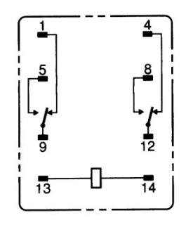
Pin Configuration and Descriptions
The MY2N relay has 8 pins, arranged as follows:
| Pin Number | Description |
|---|---|
| 1, 2 | Coil terminals (energize the relay) |
| 3, 4 | Normally Closed (NC) contact for Pole 1 |
| 5, 6 | Common terminal for Pole 1 |
| 7, 8 | Normally Open (NO) contact for Pole 1 |
Note: Pins 3, 4, 5, and 6 correspond to the first pole, while pins 7, 8, and their associated common terminal correspond to the second pole.
Usage Instructions
How to Use the MY2N in a Circuit
- Power the Coil: Connect the appropriate voltage to the coil terminals (pins 1 and 2). Ensure the voltage matches the relay's rated coil voltage (e.g., 12V DC or 24V DC).
- Connect the Load:
- For a normally open (NO) configuration, connect the load between the common terminal (pin 5 or 6) and the NO terminal (pin 7 or 8).
- For a normally closed (NC) configuration, connect the load between the common terminal and the NC terminal (pin 3 or 4).
- Switching: When the coil is energized, the relay switches from the NC contact to the NO contact, allowing current to flow through the NO terminal.
Important Considerations:
- Diode Protection: When using a DC coil, connect a flyback diode across the coil terminals to protect the circuit from voltage spikes caused by the collapsing magnetic field when the relay is de-energized.
- Contact Ratings: Ensure the load does not exceed the relay's contact rating (5A at 250V AC or 30V DC).
- Mounting: Secure the relay in a socket or PCB mount to ensure stable operation.
Example: Using MY2N with Arduino UNO
Below is an example of how to control the MY2N relay using an Arduino UNO:
// Define the pin connected to the relay's coil
const int relayPin = 7;

void setup() {
  pinMode(relayPin, OUTPUT); // Set the relay pin as an output
  digitalWrite(relayPin, LOW); // Ensure the relay is off initially
}

void loop() {
  digitalWrite(relayPin, HIGH); // Energize the relay
  delay(1000); // Keep the relay on for 1 second
  digitalWrite(relayPin, LOW); // De-energize the relay
  delay(1000); // Keep the relay off for 1 second
}
Note: Use a transistor and a flyback diode to drive the relay from the Arduino, as the Arduino's GPIO pins cannot supply sufficient current to directly energize the relay.
Troubleshooting and FAQs
Common Issues and Solutions:
Relay Not Switching:
- Cause: Insufficient coil voltage or current.
- Solution: Verify the coil voltage matches the relay's rated voltage. Check the power supply and connections.
Chattering or Unstable Operation:
- Cause: Noise or insufficient power supply.
- Solution: Use a decoupling capacitor across the power supply and ensure stable voltage.
Contacts Not Conducting:
- Cause: Worn-out contacts or excessive load.
- Solution: Check the load rating and replace the relay if the contacts are damaged.
Overheating:
- Cause: Exceeding the contact or coil ratings.
- Solution: Ensure the load and coil voltage are within the specified limits.
FAQs:
Q: Can the MY2N relay handle DC loads?
A: Yes, the MY2N can handle DC loads up to 30V at 5A.Q: What is the purpose of the flyback diode?
A: The flyback diode protects the driving circuit from voltage spikes generated when the relay coil is de-energized.Q: Can I use the MY2N for high-frequency switching?
A: No, the MY2N is not suitable for high-frequency switching due to mechanical limitations.Q: How do I test if the relay is working?
A: Apply the rated coil voltage to pins 1 and 2, and check for continuity between the common and NO terminals.
This concludes the documentation for the MY2N relay. For further assistance, refer to the manufacturer's datasheet or contact SMKN1GEMPOL support.