How to Use Power LED 12V 10W 0.8-0.9A: Examples, Pinouts, and Specs
Introduction
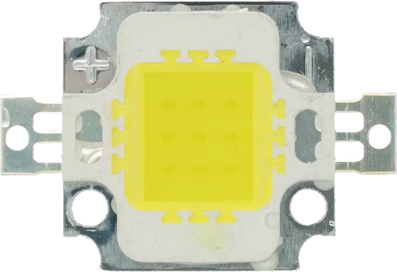
The Power LED 12V 10W 0.8-0.9A is a high-efficiency light-emitting diode designed to operate at a nominal voltage of 12V. It consumes 10 watts of power and draws a current between 0.8A and 0.9A. This LED is ideal for applications requiring bright and energy-efficient lighting, such as automotive lighting, industrial illumination, architectural lighting, and DIY projects.
Its robust design and high luminous output make it suitable for both indoor and outdoor use. The component is often used in conjunction with heat sinks and constant current drivers to ensure optimal performance and longevity.
Explore Projects Built with Power LED 12V 10W 0.8-0.9A
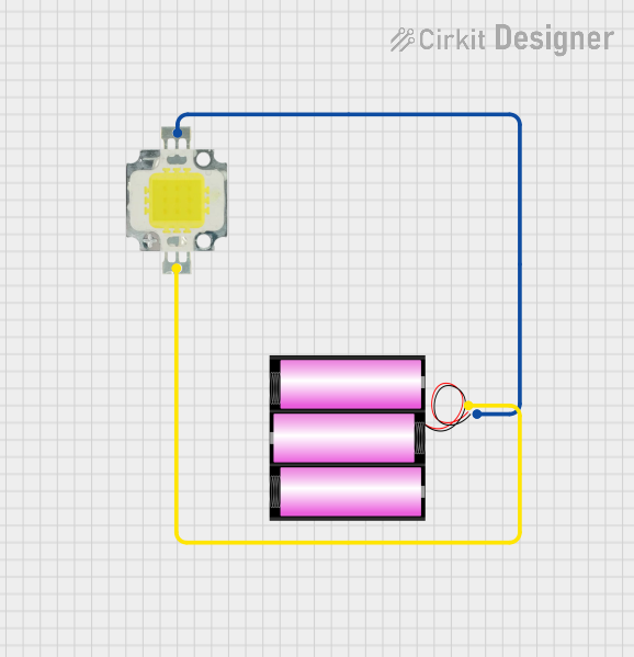
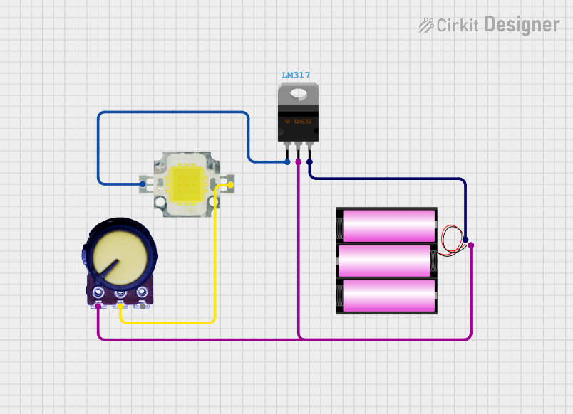

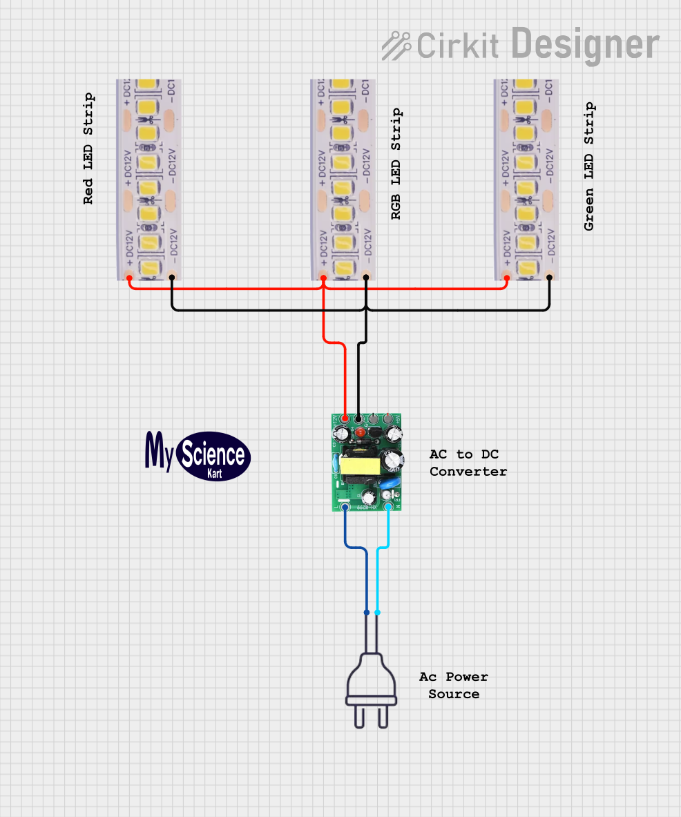
Explore Projects Built with Power LED 12V 10W 0.8-0.9A
Technical Specifications
Below are the key technical details and pin configuration for the Power LED 12V 10W 0.8-0.9A:
Key Specifications
| Parameter | Value |
|---|---|
| Nominal Voltage | 12V |
| Power Consumption | 10W |
| Current Draw | 0.8A - 0.9A |
| Luminous Flux | ~900-1000 lumens |
| Color Temperature | 3000K (Warm White) to 6500K (Cool White) |
| Operating Temperature | -20°C to +70°C |
| Lifespan | ~50,000 hours |
| Dimensions | Varies (typically ~20mm x 20mm) |
| Mounting Type | Surface-mount or screw-mount |
| Cooling Requirement | Heat sink recommended |
Pin Configuration
The Power LED typically has two terminals for connection:
| Pin Name | Description |
|---|---|
| Anode (+) | Positive terminal (connect to +12V) |
| Cathode (-) | Negative terminal (connect to ground) |
Note: Ensure correct polarity when connecting the LED to avoid damage.
Usage Instructions
How to Use the Power LED in a Circuit
- Power Supply: Use a constant voltage power supply rated at 12V. Ensure the power supply can deliver at least 1A to accommodate the LED's current draw.
- Current Regulation: To prevent overcurrent, use a constant current driver or a series resistor. A constant current driver is preferred for optimal performance and longevity.
- Heat Dissipation: Attach the LED to a heat sink to dissipate heat effectively. Overheating can reduce the lifespan of the LED.
- Wiring: Connect the anode (+) to the positive terminal of the power supply and the cathode (-) to the ground. Double-check the polarity before powering on.
Example Circuit with Arduino UNO
The Power LED can be controlled using an Arduino UNO and a MOSFET for switching. Below is an example circuit and code:
Circuit Components:
- Power LED 12V 10W
- N-channel MOSFET (e.g., IRF540N)
- 12V power supply
- 10kΩ resistor (pull-down for MOSFET gate)
- Arduino UNO
Circuit Diagram:
- Connect the MOSFET's drain to the cathode (-) of the LED.
- Connect the LED's anode (+) to the 12V power supply.
- Connect the MOSFET's source to ground.
- Connect the MOSFET's gate to an Arduino digital pin (e.g., D9) through a 10kΩ pull-down resistor.
Arduino Code:
// Power LED control using Arduino UNO
// This code uses PWM to dim the Power LED

const int ledPin = 9; // Pin connected to the MOSFET gate

void setup() {
  pinMode(ledPin, OUTPUT); // Set pin as output
}

void loop() {
  // Gradually increase brightness
  for (int brightness = 0; brightness <= 255; brightness++) {
    analogWrite(ledPin, brightness); // Set PWM duty cycle
    delay(10); // Small delay for smooth transition
  }

  // Gradually decrease brightness
  for (int brightness = 255; brightness >= 0; brightness--) {
    analogWrite(ledPin, brightness); // Set PWM duty cycle
    delay(10); // Small delay for smooth transition
  }
}
Important Notes:
- Ensure the MOSFET can handle the current (0.8-0.9A) and voltage (12V) of the LED.
- Use a heat sink for both the LED and the MOSFET if necessary.
- Do not connect the LED directly to the Arduino, as it cannot supply sufficient current.
Best Practices
- Always use a heat sink to prevent overheating.
- Avoid exceeding the rated voltage and current to ensure long-term reliability.
- Use proper insulation and mounting techniques for outdoor applications.
Troubleshooting and FAQs
Common Issues and Solutions
LED Does Not Light Up:
- Check the polarity of the connections. Reverse polarity can prevent the LED from functioning.
- Ensure the power supply is providing 12V and sufficient current.
LED Flickers:
- Verify that the power supply is stable and not overloaded.
- Check for loose connections or insufficient current regulation.
LED Overheats:
- Ensure a heat sink is properly attached to the LED.
- Check that the current is within the specified range (0.8-0.9A).
LED Burns Out Quickly:
- Avoid exceeding the rated voltage or current.
- Use a constant current driver to regulate the current.
FAQs
Q: Can I power the LED directly from a 12V battery?
A: Yes, but ensure the battery can supply at least 1A of current. For better performance, use a constant current driver.
Q: Can I dim the LED?
A: Yes, the LED can be dimmed using PWM (Pulse Width Modulation) with a MOSFET or a dedicated LED driver.
Q: Do I need a heat sink for this LED?
A: Yes, a heat sink is essential to dissipate heat and prevent damage to the LED.
Q: Can I use this LED for outdoor applications?
A: Yes, but ensure proper waterproofing and insulation for the connections.
By following this documentation, you can effectively use the Power LED 12V 10W 0.8-0.9A in your projects while ensuring optimal performance and longevity.