Cirkit Designer Logo
Cirkit Designer
Your all-in-one circuit design IDE
Home / 
Component Documentation

How to Use STM32H750 Core Board: Examples, Pinouts, and Specs

Image of STM32H750 Core Board
Cirkit Designer LogoDesign with STM32H750 Core Board in Cirkit Designer

Introduction

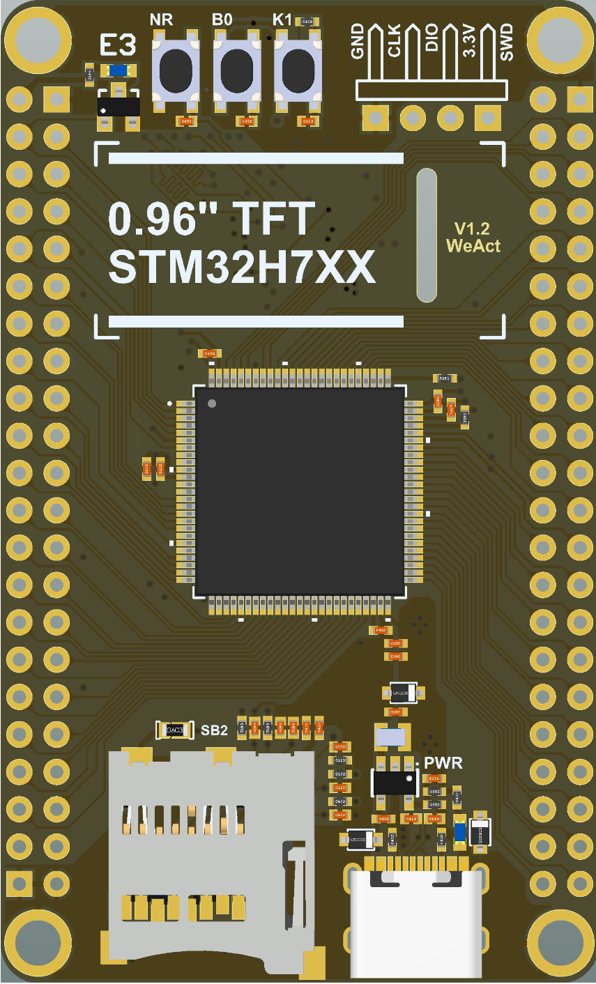
The STM32H750 Core Board, manufactured by WeAct, is a high-performance microcontroller development board based on the STM32H750 microcontroller. This microcontroller features a dual-core architecture with an ARM Cortex-M7 core running at up to 480 MHz and an ARM Cortex-M4 core running at up to 240 MHz. The board is designed for demanding applications requiring advanced processing power, extensive connectivity, and robust peripheral support.

Explore Projects Built with STM32H750 Core Board

Use Cirkit Designer to design, explore, and prototype these projects online. Some projects support real-time simulation. Click "Open Project" to start designing instantly!
STM32F103C8T6 Bluetooth-Controlled Arcade Joystick Interface
Image of RC카 조이스틱: A project utilizing STM32H750 Core Board in a practical application
This circuit features an STM32F103C8T6 microcontroller interfaced with a Bluetooth HC-06 module for wireless communication and an Adafruit Arcade Joystick for user input. The microcontroller's pins B0 and B10 are connected to the TXD and RXD pins of the Bluetooth module, enabling serial communication, while pins B14 and B15 interface with the joystick's directional controls. The circuit is powered by a battery, with power distribution managed through the microcontroller's 3.3V pin and common ground connections.
Cirkit Designer LogoOpen Project in Cirkit Designer
STM32F103C8T6-Based Spectral Sensor with ST7735S Display and Pushbutton Control
Image of ColorSensor: A project utilizing STM32H750 Core Board in a practical application
This circuit features an STM32F103C8T6 microcontroller interfaced with a China ST7735S 160x128 display and two spectral sensors (Adafruit AS7262 and AS7261). It also includes two pushbuttons for user input, with the microcontroller managing the display and sensor data processing.
Cirkit Designer LogoOpen Project in Cirkit Designer
Solar-Powered STM32-Based Automation System with Matrix Keypad and RTC
Image of soloar cleaner : A project utilizing STM32H750 Core Board in a practical application
This circuit features an STM32F103C8T6 microcontroller interfaced with a membrane matrix keypad for input, an RTC DS3231 for real-time clock functionality, and a 16x2 I2C LCD for display. It controls four 12V geared motors through two MD20 CYTRON motor drivers, with the motor power supplied by a 12V battery regulated by a buck converter. The battery is charged via a solar panel connected through a solar charge controller, ensuring a renewable energy source for the system.
Cirkit Designer LogoOpen Project in Cirkit Designer
STM32F103C8T6-Based Water Level Monitoring and Communication System with SIM900A and LoRa Connectivity
Image of water level: A project utilizing STM32H750 Core Board in a practical application
This circuit features a microcontroller (STM32F103C8T6) interfaced with a SIM900A GSM module, an HC-SR04 ultrasonic sensor, a water level sensor, and a LoRa Ra-02 SX1278 module for long-range communication. The STM32F103C8T6 is configured to communicate with the GSM module and LoRa module via serial connections, and it reads data from the ultrasonic and water level sensors. An FTDI Programmer is connected for programming and serial communication with the microcontroller.
Cirkit Designer LogoOpen Project in Cirkit Designer

Explore Projects Built with STM32H750 Core Board

Use Cirkit Designer to design, explore, and prototype these projects online. Some projects support real-time simulation. Click "Open Project" to start designing instantly!
Image of RC카 조이스틱: A project utilizing STM32H750 Core Board in a practical application
STM32F103C8T6 Bluetooth-Controlled Arcade Joystick Interface
This circuit features an STM32F103C8T6 microcontroller interfaced with a Bluetooth HC-06 module for wireless communication and an Adafruit Arcade Joystick for user input. The microcontroller's pins B0 and B10 are connected to the TXD and RXD pins of the Bluetooth module, enabling serial communication, while pins B14 and B15 interface with the joystick's directional controls. The circuit is powered by a battery, with power distribution managed through the microcontroller's 3.3V pin and common ground connections.
Cirkit Designer LogoOpen Project in Cirkit Designer
Image of ColorSensor: A project utilizing STM32H750 Core Board in a practical application
STM32F103C8T6-Based Spectral Sensor with ST7735S Display and Pushbutton Control
This circuit features an STM32F103C8T6 microcontroller interfaced with a China ST7735S 160x128 display and two spectral sensors (Adafruit AS7262 and AS7261). It also includes two pushbuttons for user input, with the microcontroller managing the display and sensor data processing.
Cirkit Designer LogoOpen Project in Cirkit Designer
Image of soloar cleaner : A project utilizing STM32H750 Core Board in a practical application
Solar-Powered STM32-Based Automation System with Matrix Keypad and RTC
This circuit features an STM32F103C8T6 microcontroller interfaced with a membrane matrix keypad for input, an RTC DS3231 for real-time clock functionality, and a 16x2 I2C LCD for display. It controls four 12V geared motors through two MD20 CYTRON motor drivers, with the motor power supplied by a 12V battery regulated by a buck converter. The battery is charged via a solar panel connected through a solar charge controller, ensuring a renewable energy source for the system.
Cirkit Designer LogoOpen Project in Cirkit Designer
Image of water level: A project utilizing STM32H750 Core Board in a practical application
STM32F103C8T6-Based Water Level Monitoring and Communication System with SIM900A and LoRa Connectivity
This circuit features a microcontroller (STM32F103C8T6) interfaced with a SIM900A GSM module, an HC-SR04 ultrasonic sensor, a water level sensor, and a LoRa Ra-02 SX1278 module for long-range communication. The STM32F103C8T6 is configured to communicate with the GSM module and LoRa module via serial connections, and it reads data from the ultrasonic and water level sensors. An FTDI Programmer is connected for programming and serial communication with the microcontroller.
Cirkit Designer LogoOpen Project in Cirkit Designer

Common Applications and Use Cases

  • Industrial automation and control systems
  • High-speed data acquisition and processing
  • IoT (Internet of Things) devices and gateways
  • Robotics and motor control
  • Audio and video processing
  • Embedded AI and machine learning applications

Technical Specifications

Key Technical Details

  • Microcontroller: STM32H750VBT6
  • Core Architecture: Dual-core ARM Cortex-M7 (480 MHz) and Cortex-M4 (240 MHz)
  • Flash Memory: 128 KB
  • RAM: 1 MB (SRAM)
  • Operating Voltage: 3.3V
  • I/O Voltage: 3.3V (5V-tolerant inputs)
  • Communication Interfaces:
    • 3x UART
    • 3x SPI
    • 3x I2C
    • 1x CAN
    • 1x USB OTG (Full-Speed)
  • Analog Inputs: 16-bit ADC (up to 3 channels)
  • Timers: 14 timers (including advanced control timers)
  • Clock Source: Internal 16 MHz RC oscillator, external crystal support
  • Power Supply: 5V via USB or external power input
  • Dimensions: 50 mm x 25 mm

Pin Configuration and Descriptions

The STM32H750 Core Board features a 40-pin header for easy integration into projects. Below is the pinout description:

Pin Number Pin Name Function Description
1 3.3V Power 3.3V power output
2 GND Ground Ground connection
3 PA0 GPIO/ADC General-purpose I/O or ADC input
4 PA1 GPIO/ADC General-purpose I/O or ADC input
5 PA2 GPIO/UART2_TX UART2 transmit pin
6 PA3 GPIO/UART2_RX UART2 receive pin
7 PB6 GPIO/I2C1_SCL I2C1 clock line
8 PB7 GPIO/I2C1_SDA I2C1 data line
9 PC13 GPIO General-purpose I/O
10 RESET Reset Board reset pin
... ... ... ...

Note: Refer to the official WeAct STM32H750 Core Board datasheet for the complete pinout.

Usage Instructions

How to Use the Component in a Circuit

  1. Powering the Board:

    • Connect the board to a 5V power source via the USB port or an external power supply.
    • Ensure the power supply is stable and within the recommended voltage range.
  2. Programming the Board:

    • Use an ST-Link programmer or USB bootloader to upload firmware.
    • Install the STM32CubeIDE or PlatformIO for development.
    • Configure the board in the IDE by selecting the STM32H750VBT6 microcontroller.
  3. Connecting Peripherals:

    • Use the GPIO pins for digital input/output.
    • Connect sensors or other analog devices to the ADC pins.
    • Use the UART, SPI, or I2C interfaces for communication with external modules.
  4. Example Circuit:

    • Connect an LED to a GPIO pin (e.g., PA0) with a current-limiting resistor.
    • Write a simple program to toggle the LED.

Important Considerations and Best Practices

  • Voltage Levels: Ensure all connected devices operate at 3.3V logic levels. Use level shifters for 5V devices.
  • Decoupling Capacitors: Add decoupling capacitors near power pins to reduce noise.
  • Clock Configuration: Configure the clock source and frequency in the firmware for optimal performance.
  • Debugging: Use the SWD (Serial Wire Debug) interface for debugging and troubleshooting.

Example Code for Arduino IDE

The STM32H750 Core Board can be programmed using the Arduino IDE with the STM32 core installed. Below is an example code to blink an LED connected to pin PA0:

// Include the STM32 HAL library
#include <Arduino.h>

// Define the LED pin
#define LED_PIN PA0

void setup() {
  // Initialize the LED pin as an output
  pinMode(LED_PIN, OUTPUT);
}

void loop() {
  // Turn the LED on
  digitalWrite(LED_PIN, HIGH);
  delay(500); // Wait for 500 milliseconds

  // Turn the LED off
  digitalWrite(LED_PIN, LOW);
  delay(500); // Wait for 500 milliseconds
}

Note: Install the STM32 core for Arduino from the Boards Manager before uploading the code.

Troubleshooting and FAQs

Common Issues and Solutions

  1. Board Not Detected by IDE:

    • Ensure the correct drivers for the ST-Link or USB bootloader are installed.
    • Check the USB cable for proper connection and functionality.
  2. Program Upload Fails:

    • Verify the board is in bootloader mode (if using USB bootloader).
    • Check the ST-Link connection and ensure the correct COM port is selected.
  3. Peripheral Not Working:

    • Double-check the pin connections and configurations in the firmware.
    • Ensure the peripheral is powered and operating within the correct voltage range.
  4. Board Overheating:

    • Verify the power supply voltage and current are within the recommended range.
    • Avoid short circuits on the GPIO pins.

FAQs

Q1: Can I use the STM32H750 Core Board with 5V sensors?
A1: Yes, but you must use level shifters to convert the 5V logic levels to 3.3V.

Q2: How do I reset the board?
A2: Press the RESET button on the board or toggle the RESET pin.

Q3: What is the maximum clock speed of the STM32H750?
A3: The ARM Cortex-M7 core can run at up to 480 MHz, while the Cortex-M4 core can run at up to 240 MHz.

Q4: Can I use the board for machine learning applications?
A4: Yes, the STM32H750's high-performance architecture makes it suitable for embedded AI and machine learning tasks.

For additional support, refer to the official WeAct documentation or community forums.