How to Use 5 pin relimate connector: Examples, Pinouts, and Specs
Introduction
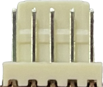
The 5 Pin Relimate Connector is a versatile and commonly used connector in electronic circuits. It is designed to provide a secure and reliable connection for up to five conductive pins. The connector is characterized by its ease of use, allowing for simple insertion and removal of wires, which facilitates quick assembly and disassembly in various applications. It is often used in prototyping, hobby electronics, and in commercial products for connecting sensors, actuators, and other peripherals to control boards such as the Arduino UNO.
Explore Projects Built with 5 pin relimate connector


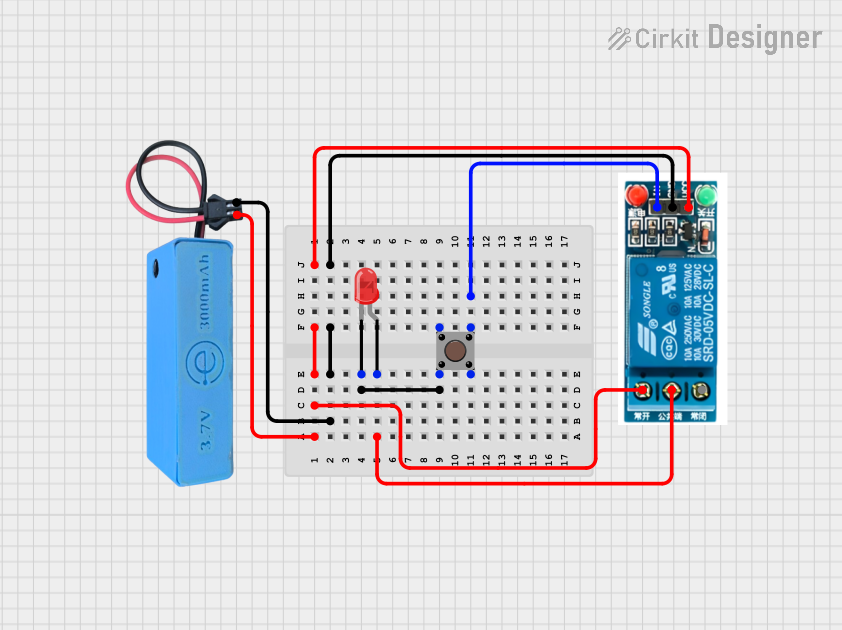
Explore Projects Built with 5 pin relimate connector
Common Applications and Use Cases
- Connecting microcontroller boards to external sensors
- Interfacing actuators like motors or servos with driver circuits
- Establishing connections between modular electronic systems
- Use in robotics for signal and power transmission
- Wiring control interfaces for user input devices
Technical Specifications
Key Technical Details
- Voltage Rating: Typically up to 250V
- Current Rating: Up to 1A per pin (varies by manufacturer)
- Contact Resistance: Typically less than 20mΩ
- Insulation Resistance: Typically greater than 1000MΩ
- Operating Temperature: -25°C to 85°C (varies by manufacturer)
Pin Configuration and Descriptions
| Pin Number | Description | Notes |
|---|---|---|
| 1 | Signal/Data/Power | Function varies by application |
| 2 | Signal/Data/Power | Function varies by application |
| 3 | Signal/Data/Power | Function varies by application |
| 4 | Signal/Data/Power | Function varies by application |
| 5 | Signal/Data/Power | Function varies by application |
Note: The actual pinout for a specific application will depend on the circuit design and the roles assigned to each pin.
Usage Instructions
How to Use the Component in a Circuit
- Identify Pin Functions: Determine the function of each pin based on your circuit design (e.g., power supply, ground, signal).
- Wire Preparation: Strip the ends of the wires to be connected and, if necessary, tin them with solder.
- Insertion: Insert the wires into the corresponding terminals of the relimate connector. Ensure a snug fit.
- Securing Wires: If applicable, use a crimping tool to secure the wires in place.
- Connection to Board: Connect the other end of the relimate connector to the corresponding female or male header on the board or device.
Important Considerations and Best Practices
- Polarity: Always be mindful of the polarity when connecting power lines to avoid short circuits or damage to components.
- Signal Integrity: For signal pins, ensure that the connections are secure to prevent intermittent connections that could lead to signal noise or data corruption.
- Wire Gauge: Use an appropriate wire gauge that matches the current rating of the connector to prevent overheating.
- Inspection: After assembly, inspect the connections for any loose wires or potential shorts.
Troubleshooting and FAQs
Common Issues Users Might Face
- Loose Connections: If a wire is not properly secured, it may lead to intermittent or failed connections.
- Incorrect Wiring: Miswiring can cause malfunction of the circuit or damage to the components.
- Physical Damage: Over-stressing the connector can lead to physical damage, affecting its functionality.
Solutions and Tips for Troubleshooting
- Double-Check Connections: Ensure all wires are properly inserted and secured in the connector.
- Verify Polarity: Re-examine the wiring to confirm correct polarity, especially for power connections.
- Visual Inspection: Look for any signs of damage or wear on the connector and replace it if necessary.
FAQs
Q: Can I use the 5 Pin Relimate Connector for high-current applications? A: No, the relimate connector is typically rated for low current applications, usually up to 1A per pin.
Q: Is the connector reusable? A: Yes, the relimate connector can be reused, but care should be taken to avoid damaging the pins or housing during wire removal.
Q: How do I know if my connection is secure? A: A secure connection will typically have no visible metal of the inserted wire, and the wire should not be able to be pulled out easily without using a de-pinning tool.
Q: Are relimate connectors polarized? A: Some relimate connectors are polarized to prevent incorrect connections. Check the datasheet or product details of the specific connector you are using.
Note: Always refer to the manufacturer's datasheet for the most accurate and detailed information about the specific relimate connector you are using.