How to Use pin: Examples, Pinouts, and Specs

Introduction
A pin is a small metal or plastic fastener used to connect or secure components in a circuit. It serves as a critical point of electrical connection, enabling the flow of current between different parts of an electronic system. Pins are commonly found in connectors, integrated circuits (ICs), headers, and other electronic components. They are essential for creating reliable and stable connections in both prototyping and production environments.
Explore Projects Built with pin


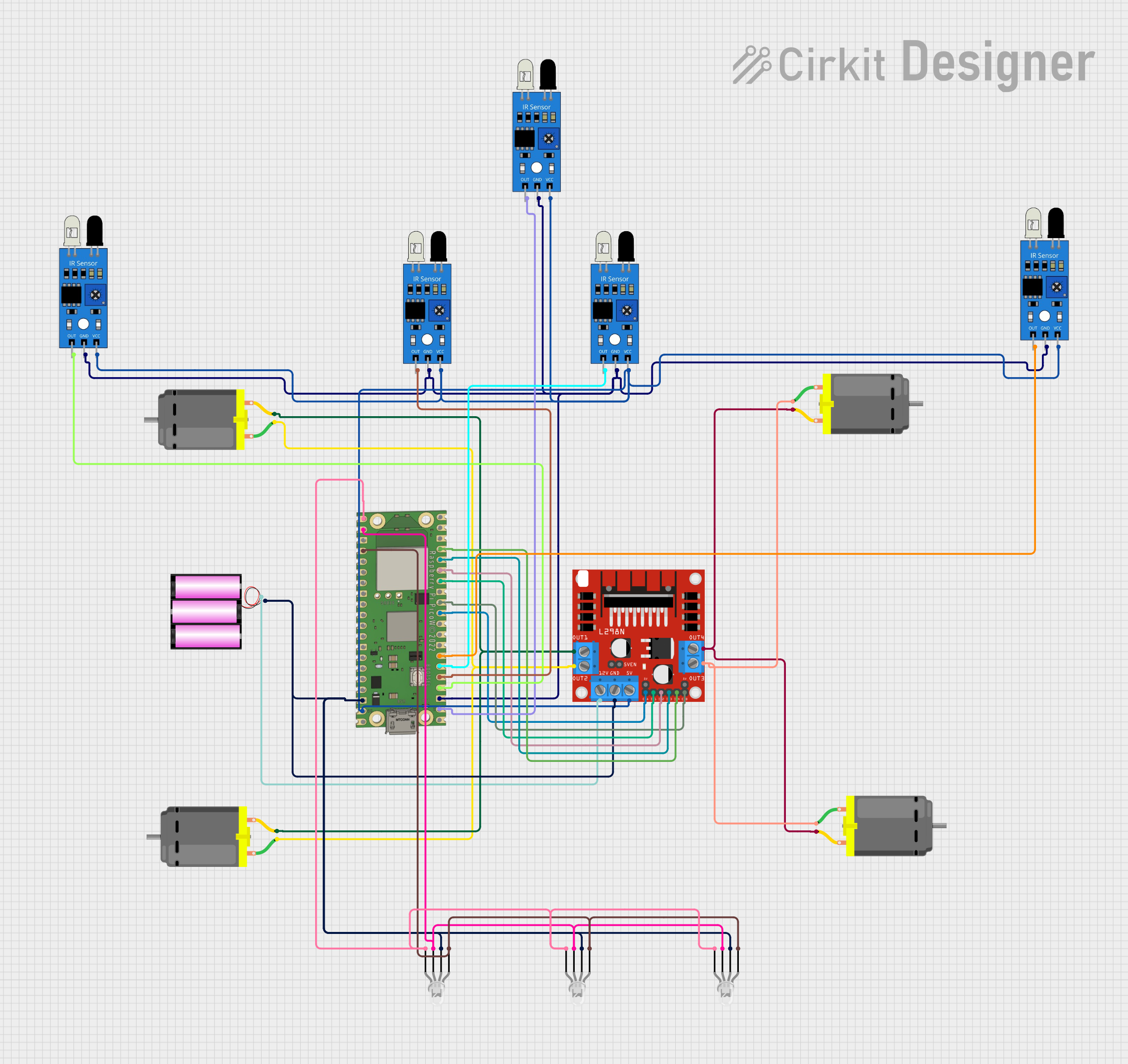
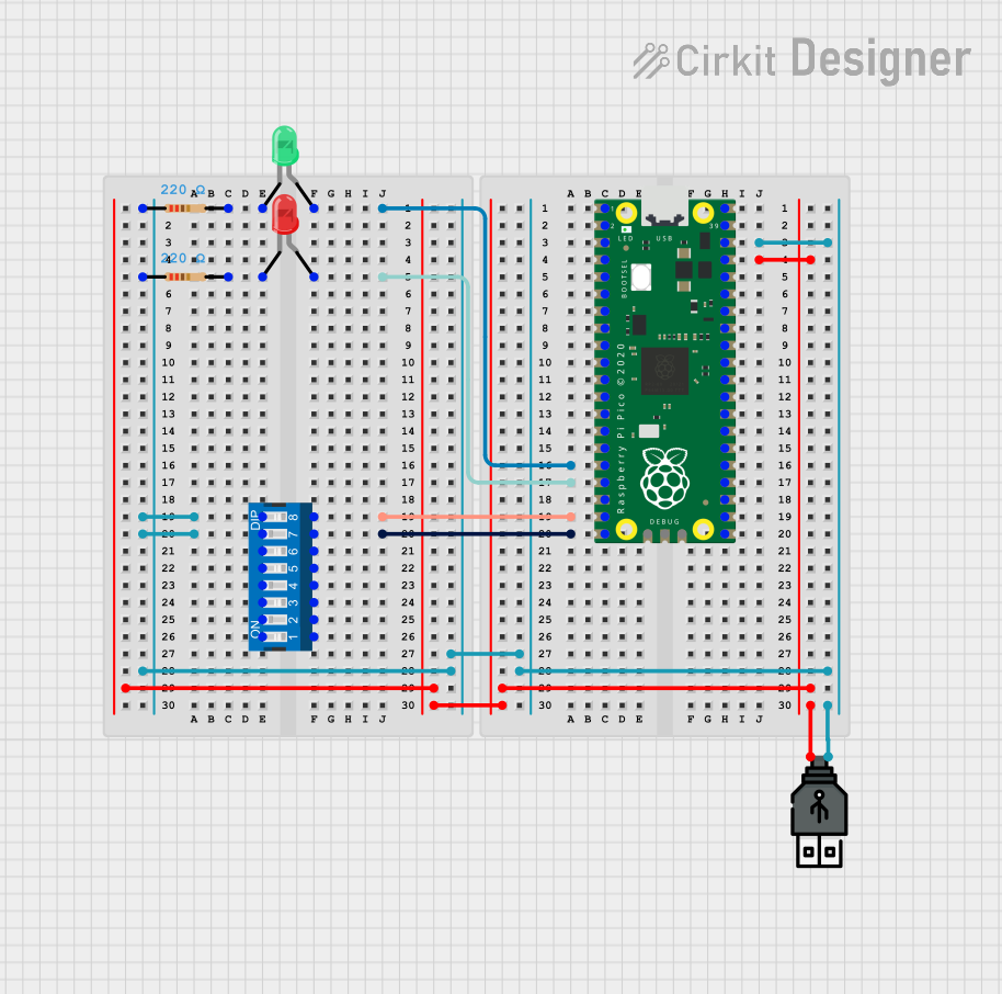
Explore Projects Built with pin
Common Applications and Use Cases
- Prototyping and Breadboarding: Pins are used to connect components on breadboards or prototyping boards.
- Integrated Circuits (ICs): Pins provide electrical connections for ICs to interface with other components.
- Connectors and Headers: Pins are used in connectors to establish connections between cables and PCBs.
- Soldering and PCB Assembly: Pins are soldered onto PCBs to create permanent connections.
- Test Points: Pins can serve as test points for debugging and measuring signals in a circuit.
Technical Specifications
Pins come in various shapes, sizes, and materials depending on their application. Below are the general technical details for standard pins:
General Specifications
| Parameter | Description |
|---|---|
| Material | Typically made of copper, brass, or steel, often plated with tin or gold |
| Diameter | Ranges from 0.5 mm to 2.54 mm (standard sizes for electronic applications) |
| Length | Varies from 5 mm to 50 mm depending on the use case |
| Current Rating | Typically 1 A to 5 A, depending on the material and size |
| Voltage Rating | Up to 250 V for standard pins |
| Insulation Resistance | >100 MΩ (for insulated pins) |
| Operating Temperature | -40°C to +125°C |
Pin Configuration and Descriptions
Pins are often part of larger components like headers or ICs. Below is an example of a pin configuration for a standard 2x4 header:
| Pin Number | Description |
|---|---|
| 1 | Ground (GND) |
| 2 | Power (VCC) |
| 3 | Signal Line 1 |
| 4 | Signal Line 2 |
| 5 | Signal Line 3 |
| 6 | Signal Line 4 |
| 7 | Reserved |
| 8 | Reserved |
Usage Instructions
How to Use Pins in a Circuit
- Identify the Pin Type: Determine whether the pin is part of a header, connector, or standalone.
- Insert or Solder:
- For breadboards, insert the pin into the appropriate hole.
- For PCBs, solder the pin securely to the designated pad.
- Connect Components: Use wires, connectors, or solder to establish connections between pins and other components.
- Ensure Proper Orientation: For polarized pins (e.g., power and ground), ensure correct orientation to avoid damage.
Important Considerations and Best Practices
- Material Selection: Use gold-plated pins for high-reliability applications to prevent corrosion.
- Current and Voltage Ratings: Ensure the pin can handle the required current and voltage to avoid overheating or failure.
- Mechanical Stress: Avoid excessive bending or force on pins to prevent damage.
- Soldering: Use appropriate soldering techniques to ensure a strong and reliable connection.
- Insulation: For high-voltage applications, use insulated pins to prevent short circuits.
Example: Using Pins with an Arduino UNO
Pins are commonly used to connect sensors, modules, or other components to an Arduino UNO. Below is an example of connecting a sensor using pins:
// Example: Reading a digital signal from a sensor connected via a pin

const int sensorPin = 2; // Pin 2 is connected to the sensor's output
int sensorValue = 0;     // Variable to store the sensor's value

void setup() {
  pinMode(sensorPin, INPUT); // Set pin 2 as an input
  Serial.begin(9600);        // Initialize serial communication
}

void loop() {
  sensorValue = digitalRead(sensorPin); // Read the sensor's digital output
  Serial.println(sensorValue);         // Print the value to the Serial Monitor
  delay(500);                          // Wait for 500 ms before the next reading
}
Troubleshooting and FAQs
Common Issues
- Loose Connections: Pins may not make proper contact with the circuit.
- Solution: Ensure the pin is securely inserted or soldered.
- Corrosion: Pins may corrode over time, leading to poor conductivity.
- Solution: Use gold-plated pins or clean the pins with isopropyl alcohol.
- Bent Pins: Pins may bend during handling or insertion.
- Solution: Carefully straighten the pin using needle-nose pliers.
- Overheating: Pins may overheat if the current exceeds their rating.
- Solution: Verify the current rating and use appropriate pins for the application.
FAQs
Q: Can I reuse pins after desoldering?
A: Yes, but ensure the pins are clean and straight before reusing them.
Q: How do I prevent pins from bending during insertion?
A: Use a pin alignment tool or carefully guide the pins into the socket or PCB.
Q: What is the difference between male and female pins?
A: Male pins protrude outward and are designed to fit into female sockets, which have recessed contacts.
Q: Can pins handle AC signals?
A: Yes, as long as the voltage and current ratings are not exceeded.