How to Use Adafruit Feather M0 Adalogger: Examples, Pinouts, and Specs
Introduction
The Adafruit Feather M0 Adalogger is a compact microcontroller board built around the ARM Cortex-M0 processor. It is designed for low-power applications and features an integrated SD card slot, making it ideal for data logging tasks. This versatile board is part of the Adafruit Feather ecosystem, which includes a wide range of compatible add-ons and accessories.
Explore Projects Built with Adafruit Feather M0 Adalogger

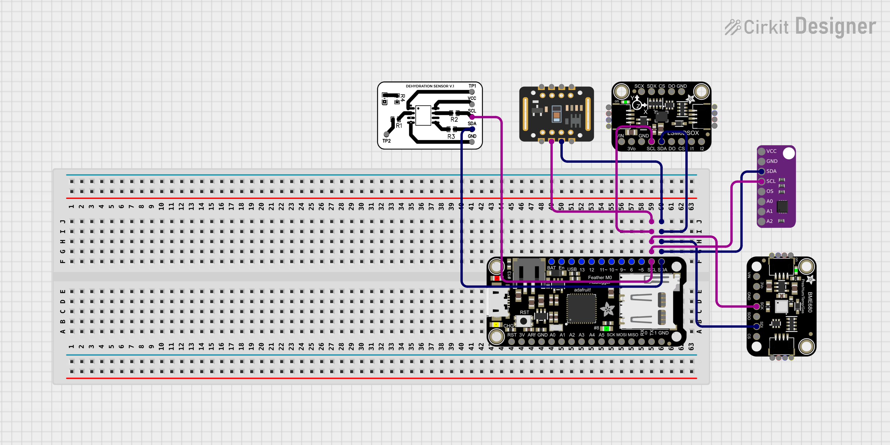
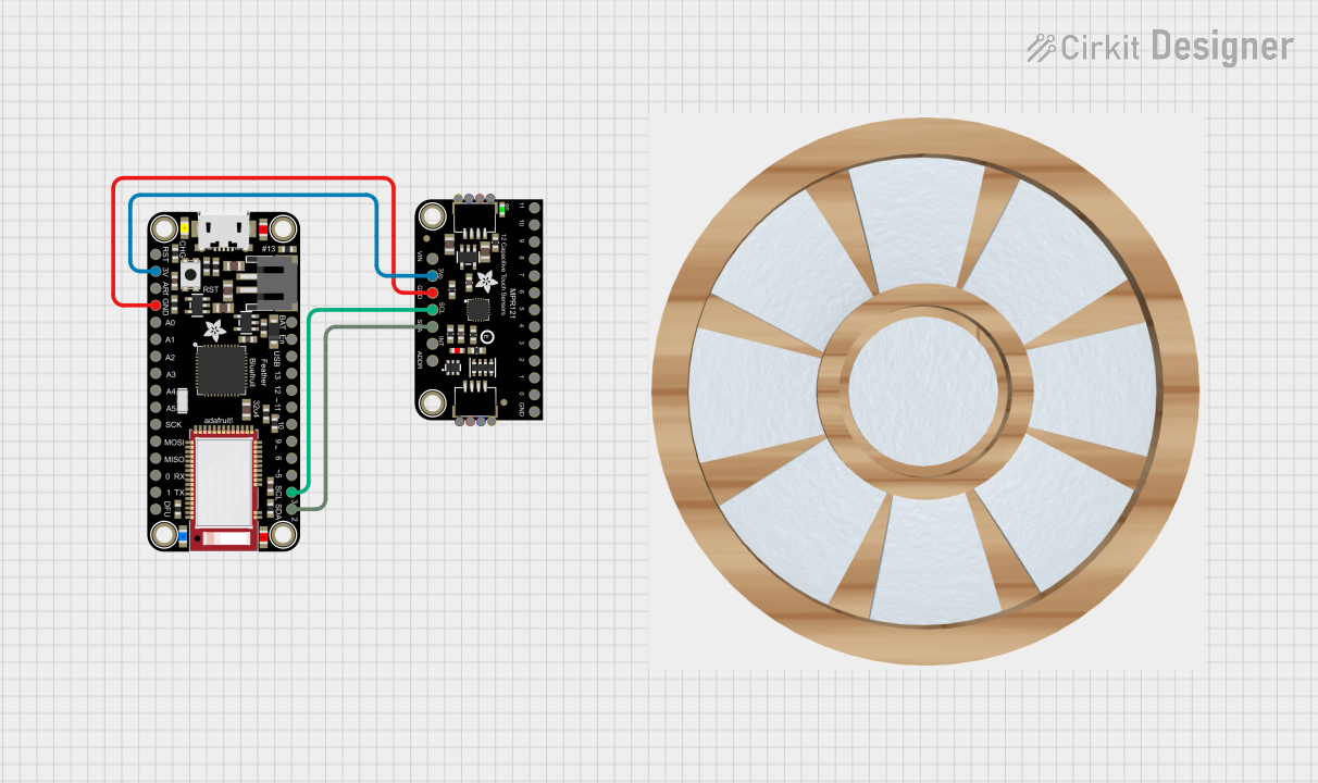
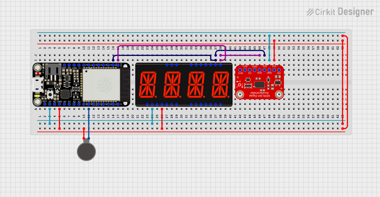
Explore Projects Built with Adafruit Feather M0 Adalogger
Common Applications and Use Cases
- Environmental data logging (e.g., temperature, humidity, pressure)
- IoT (Internet of Things) projects requiring low power consumption
- Portable devices with battery-powered operation
- Prototyping and development of sensor-based systems
- Projects requiring SD card storage for large datasets
Technical Specifications
Key Technical Details
- Microcontroller: ATSAMD21G18 ARM Cortex-M0, 32-bit, 48 MHz
- Flash Memory: 256 KB
- SRAM: 32 KB
- Operating Voltage: 3.3V
- Input Voltage: 3.7V (via LiPo battery) or 5V (via USB)
- Digital I/O Pins: 20 (with 8 PWM outputs)
- Analog Input Pins: 6 (12-bit ADC)
- UART, SPI, I2C: Supported
- SD Card Slot: Built-in, supports microSD cards
- Battery Connector: JST 2-pin for 3.7V LiPo batteries
- USB Interface: Micro-USB for programming and power
- Dimensions: 51mm x 23mm x 8mm
- Weight: 5.7g
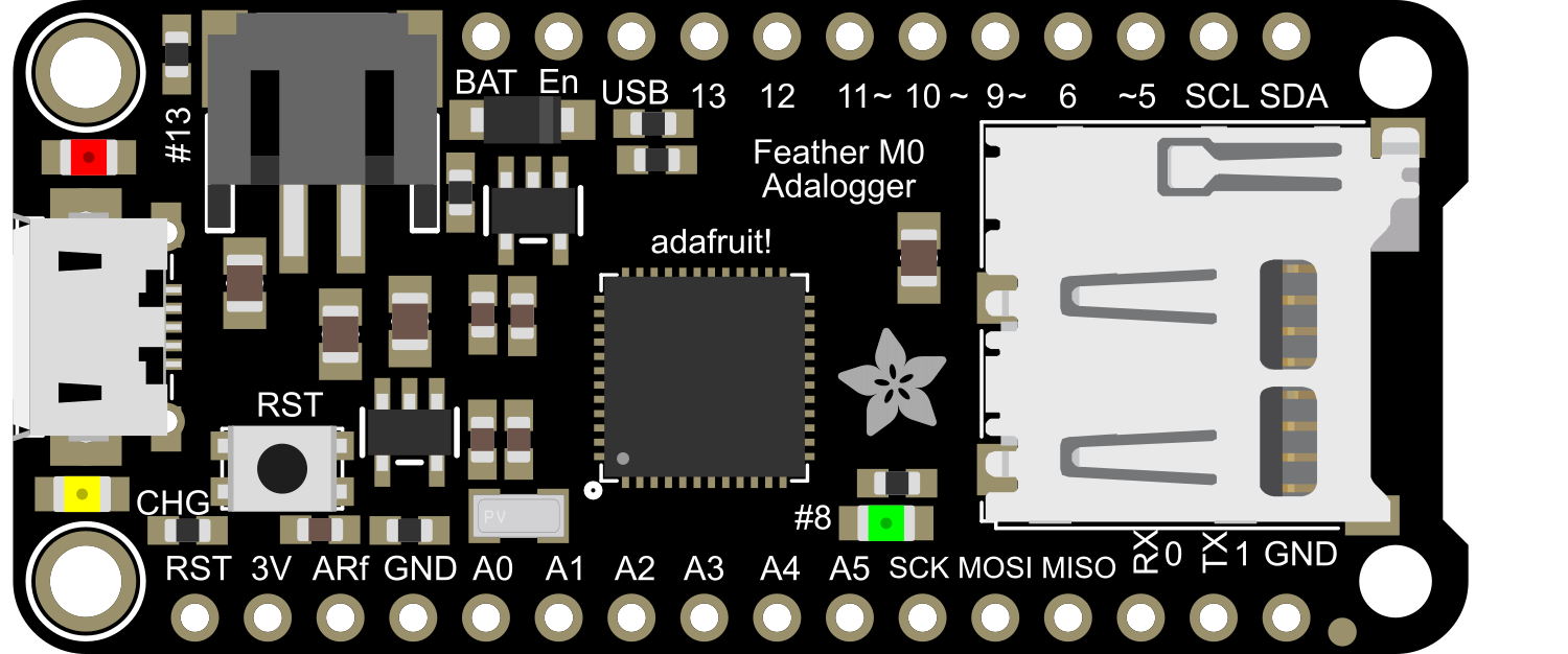
Pin Configuration and Descriptions
The Adafruit Feather M0 Adalogger has a total of 28 pins, including power, digital, and analog pins. Below is a detailed description of the pinout:
| Pin | Name | Description |
|---|---|---|
| 1 | USB | Micro-USB connector for power and programming |
| 2 | BAT | Battery input (3.7V LiPo) |
| 3 | 3V3 | 3.3V regulated output |
| 4 | GND | Ground |
| 5 | A0 - A5 | Analog input pins (12-bit ADC, also configurable as digital I/O) |
| 6 | D0 - D13 | Digital I/O pins (D3, D5, D6, D9, D10, D11, D12 support PWM) |
| 7 | SDA | I2C data line (shared with D20) |
| 8 | SCL | I2C clock line (shared with D21) |
| 9 | RX | UART receive (D0) |
| 10 | TX | UART transmit (D1) |
| 11 | SD_CS | Chip select for the SD card |
| 12 | RST | Reset pin (active low) |
| 13 | EN | Enable pin for 3.3V regulator |
| 14 | LIPO | LiPo battery charging status indicator |
Usage Instructions
How to Use the Component in a Circuit
Powering the Board:
- Connect a 3.7V LiPo battery to the JST connector for portable operation.
- Alternatively, power the board via the Micro-USB port (5V input).
Programming the Board:
- Use the Arduino IDE with the Adafruit SAMD board package installed.
- Connect the board to your computer via a Micro-USB cable.
- Select "Adafruit Feather M0" as the board type in the Arduino IDE.
Connecting Sensors and Peripherals:
- Use the analog (A0-A5) and digital (D0-D13) pins to interface with sensors and actuators.
- For I2C devices, connect to the SDA and SCL pins.
- For SPI devices, use the SD_CS pin along with the SPI bus pins (MOSI, MISO, SCK).
Using the SD Card Slot:
- Insert a microSD card into the slot.
- Use the
SDlibrary in Arduino to read/write data to the card.
Important Considerations and Best Practices
- Ensure the board is powered off before connecting or disconnecting components.
- Use level shifters if interfacing with 5V logic devices, as the Feather M0 operates at 3.3V.
- Avoid drawing excessive current from the 3.3V pin to prevent overheating.
- Format the microSD card as FAT16 or FAT32 for compatibility with the
SDlibrary.
Example Code for Data Logging with Arduino UNO
#include <SPI.h>
#include <SD.h>

// Define the chip select pin for the SD card
const int chipSelect = 4;

void setup() {
  // Initialize serial communication for debugging
  Serial.begin(9600);
  while (!Serial) {
    // Wait for the serial port to connect
  }

  Serial.println("Initializing SD card...");

  // Check if the SD card is available
  if (!SD.begin(chipSelect)) {
    Serial.println("SD card initialization failed!");
    return;
  }
  Serial.println("SD card initialized successfully.");

  // Create or open a file on the SD card
  File dataFile = SD.open("datalog.txt", FILE_WRITE);

  // Write data to the file
  if (dataFile) {
    dataFile.println("Temperature: 25.3 C");
    dataFile.println("Humidity: 60%");
    dataFile.close(); // Close the file
    Serial.println("Data written to datalog.txt");
  } else {
    Serial.println("Error opening datalog.txt");
  }
}

void loop() {
  // Nothing to do here
}
Troubleshooting and FAQs
Common Issues and Solutions
SD Card Not Detected:
- Ensure the SD card is properly inserted into the slot.
- Verify the card is formatted as FAT16 or FAT32.
- Check the wiring of the SD_CS pin if using a custom setup.
Board Not Recognized by Computer:
- Confirm the USB cable is functional and supports data transfer.
- Install the correct USB drivers for the Adafruit Feather M0.
- Double-check the board type and port settings in the Arduino IDE.
Program Upload Fails:
- Press the reset button on the board twice to enter bootloader mode.
- Ensure no other software is using the COM port.
Overheating or Power Issues:
- Avoid drawing more than 500mA from the USB port.
- Use a properly rated LiPo battery for portable operation.
FAQs
Can I use the Feather M0 Adalogger with 5V sensors?
No, the board operates at 3.3V logic. Use level shifters for 5V devices.What is the maximum SD card size supported?
The board supports microSD cards up to 32GB formatted as FAT16 or FAT32.How do I monitor battery voltage?
Use theanalogRead()function on the A7 pin to measure the battery voltage.Can I use the board without a battery?
Yes, the board can be powered via the Micro-USB port alone.