Cirkit Designer Logo
Cirkit Designer
Your all-in-one circuit design IDE
Home / 
Component Documentation

How to Use KY-025 Modulo Reed Switch: Examples, Pinouts, and Specs

Image of KY-025 Modulo Reed Switch
Cirkit Designer LogoDesign with KY-025 Modulo Reed Switch in Cirkit Designer

Introduction

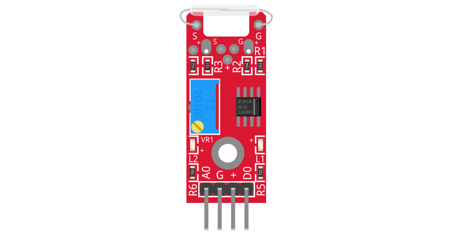
The KY-025 Modulo Reed Switch, manufactured by Arduino (Part ID: HH), is a versatile sensor module designed to detect magnetic fields. It operates using a reed switch, a small mechanical switch that closes its contacts when exposed to a magnetic field. This module is widely used in applications such as door and window sensors, security systems, and other projects requiring magnetic field detection. Its simplicity and reliability make it a popular choice for hobbyists and professionals alike.

Explore Projects Built with KY-025 Modulo Reed Switch

Use Cirkit Designer to design, explore, and prototype these projects online. Some projects support real-time simulation. Click "Open Project" to start designing instantly!
Arduino UNO Bluetooth-Controlled Security System with Reed Switch and LED Indicators
Image of fc AAA: A project utilizing KY-025 Modulo Reed Switch in a practical application
This circuit is designed as a security system that uses an Arduino UNO microcontroller to interface with a reed switch, two LEDs (red and green), and a Bluetooth module (MKE-M15). The reed switch is monitored by the Arduino to detect an open/close state, which, along with a passcode received via Bluetooth, controls the state of the LEDs: green for access granted and red for access denied. Additionally, the circuit can send an intruder alert message if the reed switch is not activated and no Bluetooth connection is present.
Cirkit Designer LogoOpen Project in Cirkit Designer
ESP32-Based Security System with RFID and Laser Tripwire
Image of CPE doorlock system: A project utilizing KY-025 Modulo Reed Switch in a practical application
This circuit is designed for a comprehensive security and access control system with motion detection, access via RFID, and a break-beam sensor. It includes a solenoid lock controlled by a relay, visual and audible alerts, and a robust power management system with solar and battery backup to ensure uninterrupted operation.
Cirkit Designer LogoOpen Project in Cirkit Designer
Arduino UNO Controlled GSM Interface with LCD Feedback and Relay Switching
Image of pascal_issac project: A project utilizing KY-025 Modulo Reed Switch in a practical application
This circuit features an Arduino UNO microcontroller interfaced with a variety of components. It controls a KY-019 relay module to switch power to a motor and communicates with a SIM800L module for cellular connectivity. User inputs are handled via a membrane matrix keypad and pushbuttons, and feedback is provided through an I2C-connected LCD display. A step-up boost converter adjusts voltage from a 12V battery to power the motor, and a 3-position switch is used for additional control.
Cirkit Designer LogoOpen Project in Cirkit Designer
Arduino Nano Controlled Relay System with Safety Interlocks
Image of HYD: A project utilizing KY-025 Modulo Reed Switch in a practical application
This circuit includes an Arduino Nano microcontroller interfaced with multiple pushbuttons, limit switches, an emergency stop, a 2-channel relay module, and a 1-channel relay module. The Arduino controls the relay modules based on inputs from the pushbuttons and limit switches, which likely serve as user interfaces and position or safety sensors. The circuit is powered by a 5V power supply unit (PSU), which is connected to an AC supply, and the emergency stop is configured to potentially interrupt the circuit for safety purposes.
Cirkit Designer LogoOpen Project in Cirkit Designer

Explore Projects Built with KY-025 Modulo Reed Switch

Use Cirkit Designer to design, explore, and prototype these projects online. Some projects support real-time simulation. Click "Open Project" to start designing instantly!
Image of fc AAA: A project utilizing KY-025 Modulo Reed Switch in a practical application
Arduino UNO Bluetooth-Controlled Security System with Reed Switch and LED Indicators
This circuit is designed as a security system that uses an Arduino UNO microcontroller to interface with a reed switch, two LEDs (red and green), and a Bluetooth module (MKE-M15). The reed switch is monitored by the Arduino to detect an open/close state, which, along with a passcode received via Bluetooth, controls the state of the LEDs: green for access granted and red for access denied. Additionally, the circuit can send an intruder alert message if the reed switch is not activated and no Bluetooth connection is present.
Cirkit Designer LogoOpen Project in Cirkit Designer
Image of CPE doorlock system: A project utilizing KY-025 Modulo Reed Switch in a practical application
ESP32-Based Security System with RFID and Laser Tripwire
This circuit is designed for a comprehensive security and access control system with motion detection, access via RFID, and a break-beam sensor. It includes a solenoid lock controlled by a relay, visual and audible alerts, and a robust power management system with solar and battery backup to ensure uninterrupted operation.
Cirkit Designer LogoOpen Project in Cirkit Designer
Image of pascal_issac project: A project utilizing KY-025 Modulo Reed Switch in a practical application
Arduino UNO Controlled GSM Interface with LCD Feedback and Relay Switching
This circuit features an Arduino UNO microcontroller interfaced with a variety of components. It controls a KY-019 relay module to switch power to a motor and communicates with a SIM800L module for cellular connectivity. User inputs are handled via a membrane matrix keypad and pushbuttons, and feedback is provided through an I2C-connected LCD display. A step-up boost converter adjusts voltage from a 12V battery to power the motor, and a 3-position switch is used for additional control.
Cirkit Designer LogoOpen Project in Cirkit Designer
Image of HYD: A project utilizing KY-025 Modulo Reed Switch in a practical application
Arduino Nano Controlled Relay System with Safety Interlocks
This circuit includes an Arduino Nano microcontroller interfaced with multiple pushbuttons, limit switches, an emergency stop, a 2-channel relay module, and a 1-channel relay module. The Arduino controls the relay modules based on inputs from the pushbuttons and limit switches, which likely serve as user interfaces and position or safety sensors. The circuit is powered by a 5V power supply unit (PSU), which is connected to an AC supply, and the emergency stop is configured to potentially interrupt the circuit for safety purposes.
Cirkit Designer LogoOpen Project in Cirkit Designer

Technical Specifications

The KY-025 Modulo Reed Switch has the following technical specifications:

  • Operating Voltage: 3.3V to 5V
  • Output Type: Digital and Analog
  • Dimensions: 32mm x 14mm x 10mm
  • Detection Range: Up to 10mm (depending on the strength of the magnet)
  • Operating Temperature: -40°C to +85°C
  • Power Consumption: Low power consumption suitable for battery-powered applications

Pin Configuration and Descriptions

The KY-025 module has three pins, as described in the table below:

Pin Name Description
1 Signal (S) Outputs the signal. Can be connected to a digital or analog input on a microcontroller.
2 VCC Power supply pin. Connect to 3.3V or 5V.
3 GND Ground pin. Connect to the ground of the circuit.

Usage Instructions

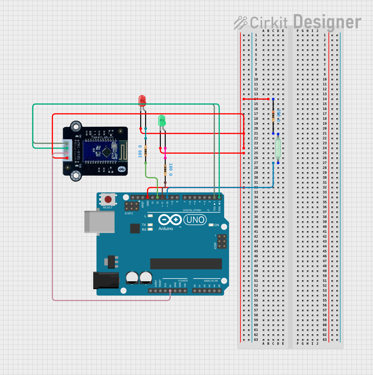
How to Use the KY-025 Modulo Reed Switch in a Circuit

  1. Wiring the Module:

    • Connect the VCC pin to the 5V pin on your microcontroller (e.g., Arduino UNO).
    • Connect the GND pin to the ground (GND) of your microcontroller.
    • Connect the Signal (S) pin to a digital input pin (e.g., D2) or an analog input pin (e.g., A0) on your microcontroller.
  2. Magnetic Field Detection:

    • When a magnet is brought near the reed switch, the contacts inside the switch close, and the module outputs a signal.
    • The digital output pin will go HIGH (1) when a magnetic field is detected and LOW (0) otherwise.
    • The analog output pin provides a voltage proportional to the strength of the magnetic field.
  3. Example Circuit:

    • Place the KY-025 module on a breadboard.
    • Use jumper wires to connect the module to your microcontroller as described above.
    • Optionally, connect an LED to the digital output pin to visually indicate magnetic field detection.

Important Considerations and Best Practices

  • Avoid exposing the module to strong vibrations or shocks, as this may damage the reed switch.
  • Ensure the magnet used is within the detection range of the module for reliable operation.
  • Use pull-up or pull-down resistors if necessary to stabilize the digital output signal.
  • Keep the module away from strong electromagnetic interference (EMI) sources to prevent false triggering.

Arduino UNO Example Code

Below is an example code snippet to use the KY-025 Modulo Reed Switch with an Arduino UNO:

// KY-025 Reed Switch Example Code
// Connect the Signal pin to digital pin 2 on the Arduino UNO
// Connect VCC to 5V and GND to GND

const int reedSwitchPin = 2; // Pin connected to the KY-025 Signal pin
const int ledPin = 13;       // Built-in LED pin for visual indication

void setup() {
  pinMode(reedSwitchPin, INPUT); // Set reed switch pin as input
  pinMode(ledPin, OUTPUT);       // Set LED pin as output
  Serial.begin(9600);           // Initialize serial communication
}

void loop() {
  int reedState = digitalRead(reedSwitchPin); // Read the state of the reed switch

  if (reedState == HIGH) {
    // If magnetic field is detected, turn on the LED
    digitalWrite(ledPin, HIGH);
    Serial.println("Magnetic field detected!");
  } else {
    // If no magnetic field is detected, turn off the LED
    digitalWrite(ledPin, LOW);
    Serial.println("No magnetic field detected.");
  }

  delay(500); // Wait for 500ms before reading again
}

Troubleshooting and FAQs

Common Issues and Solutions

  1. The module does not detect the magnet:

    • Ensure the magnet is within the detection range of the reed switch.
    • Verify that the module is properly powered (3.3V or 5V).
    • Check the wiring connections for loose or incorrect connections.
  2. False triggering or unstable output:

    • Use a pull-up or pull-down resistor to stabilize the digital output signal.
    • Keep the module away from sources of electromagnetic interference (EMI).
  3. No output signal:

    • Confirm that the reed switch is not physically damaged.
    • Test the module with a multimeter to ensure the reed switch closes when a magnet is nearby.

FAQs

Q: Can the KY-025 module detect the polarity of a magnet?
A: No, the KY-025 module cannot detect the polarity of a magnet. It only detects the presence of a magnetic field.

Q: Can I use the KY-025 module with a 3.3V microcontroller?
A: Yes, the KY-025 module is compatible with both 3.3V and 5V microcontrollers.

Q: What type of magnet should I use with the KY-025 module?
A: Any small neodymium or ferrite magnet should work, as long as it is within the detection range of the reed switch.

Q: Is the KY-025 module suitable for outdoor use?
A: The module is not weatherproof. If used outdoors, it should be enclosed in a protective casing to prevent damage from moisture or dust.