Cirkit Designer Logo
Cirkit Designer
Your all-in-one circuit design IDE
Home / 
Component Documentation

How to Use USB Female: Examples, Pinouts, and Specs

Image of USB Female
Cirkit Designer LogoDesign with USB Female in Cirkit Designer

Introduction

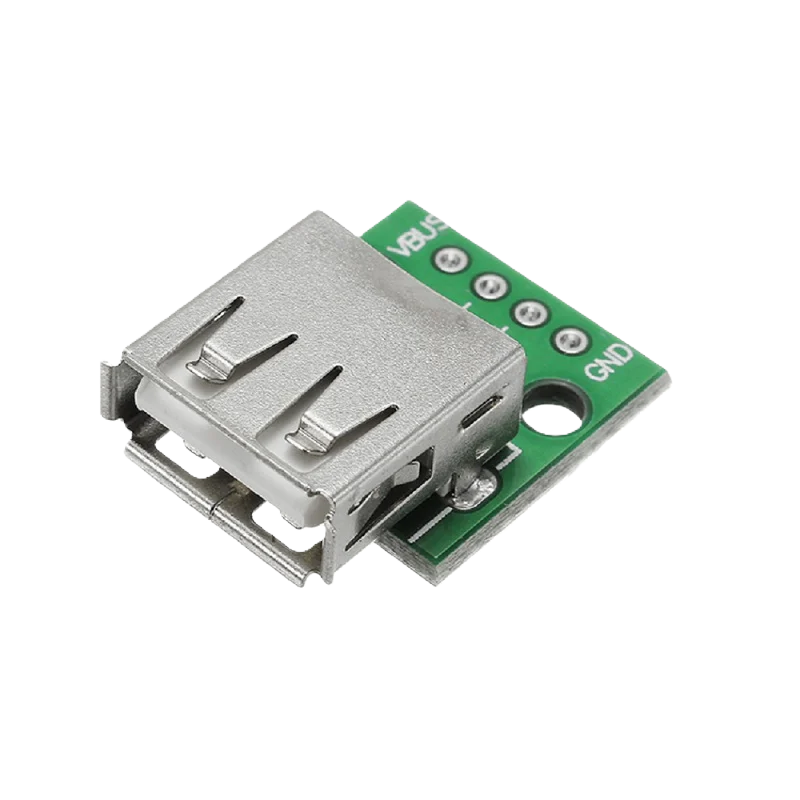
A USB (Universal Serial Bus) female connector is a standard interface used in a wide range of electronic devices. It serves as a receptacle for a USB male connector, facilitating both power supply and data transfer between devices. Common applications include connecting peripherals such as keyboards, mice, printers, and external storage devices to computers, as well as charging and data synchronization for mobile devices.

Explore Projects Built with USB Female

Use Cirkit Designer to design, explore, and prototype these projects online. Some projects support real-time simulation. Click "Open Project" to start designing instantly!
USB Power Supply with Overcurrent Protection
Image of USB Charging port: A project utilizing USB Female in a practical application
This circuit is designed to step down voltage from a 12V battery to a lower voltage suitable for USB devices. It includes a buck converter connected to the battery through a fuse and fuse holder for overcurrent protection. The output of the buck converter is connected to a USB female port, providing a regulated power supply for USB-powered devices.
Cirkit Designer LogoOpen Project in Cirkit Designer
Beelink Mini S12 N95 and Arduino UNO Based Fingerprint Authentication System with ESP32 CAM
Image of design 3: A project utilizing USB Female in a practical application
This circuit features a Beelink MINI S12 N95 computer connected to a 7-inch display via HDMI for video output and two USB connections for power and touch screen functionality. An Arduino UNO is interfaced with a fingerprint scanner for biometric input. The Beelink MINI S12 N95 is powered by a PC power supply, which in turn is connected to a 240V power source. Additionally, an ESP32 CAM module is powered and programmed via a USB plug and an FTDI programmer, respectively, for wireless camera capabilities.
Cirkit Designer LogoOpen Project in Cirkit Designer
FTDI to UART Adapter with J26 Connector
Image of J26 CLOSEUP: A project utilizing USB Female in a practical application
This circuit connects an FTDI USB-to-serial converter to a standard serial interface via a J26 connector. It facilitates serial communication by linking the ground, transmit, receive, data terminal ready, and request to send signals between the FTDI chip and the J26 connector.
Cirkit Designer LogoOpen Project in Cirkit Designer
USB Type-C Powered LED Circuit with Resistor
Image of Scheme1: A project utilizing USB Female in a practical application
This circuit consists of a USB Type-C port providing power to a red LED through a 1000 Ohm resistor. The resistor limits the current flowing through the LED, which lights up when the circuit is powered.
Cirkit Designer LogoOpen Project in Cirkit Designer

Explore Projects Built with USB Female

Use Cirkit Designer to design, explore, and prototype these projects online. Some projects support real-time simulation. Click "Open Project" to start designing instantly!
Image of USB Charging port: A project utilizing USB Female in a practical application
USB Power Supply with Overcurrent Protection
This circuit is designed to step down voltage from a 12V battery to a lower voltage suitable for USB devices. It includes a buck converter connected to the battery through a fuse and fuse holder for overcurrent protection. The output of the buck converter is connected to a USB female port, providing a regulated power supply for USB-powered devices.
Cirkit Designer LogoOpen Project in Cirkit Designer
Image of design 3: A project utilizing USB Female in a practical application
Beelink Mini S12 N95 and Arduino UNO Based Fingerprint Authentication System with ESP32 CAM
This circuit features a Beelink MINI S12 N95 computer connected to a 7-inch display via HDMI for video output and two USB connections for power and touch screen functionality. An Arduino UNO is interfaced with a fingerprint scanner for biometric input. The Beelink MINI S12 N95 is powered by a PC power supply, which in turn is connected to a 240V power source. Additionally, an ESP32 CAM module is powered and programmed via a USB plug and an FTDI programmer, respectively, for wireless camera capabilities.
Cirkit Designer LogoOpen Project in Cirkit Designer
Image of J26 CLOSEUP: A project utilizing USB Female in a practical application
FTDI to UART Adapter with J26 Connector
This circuit connects an FTDI USB-to-serial converter to a standard serial interface via a J26 connector. It facilitates serial communication by linking the ground, transmit, receive, data terminal ready, and request to send signals between the FTDI chip and the J26 connector.
Cirkit Designer LogoOpen Project in Cirkit Designer
Image of Scheme1: A project utilizing USB Female in a practical application
USB Type-C Powered LED Circuit with Resistor
This circuit consists of a USB Type-C port providing power to a red LED through a 1000 Ohm resistor. The resistor limits the current flowing through the LED, which lights up when the circuit is powered.
Cirkit Designer LogoOpen Project in Cirkit Designer

Technical Specifications

General Characteristics

  • Type: USB Female Connector
  • Versions: USB 1.1, USB 2.0, USB 3.0, USB 3.1, USB-C, etc.
  • Data Transfer Rate: Varies by USB version (e.g., up to 480 Mbps for USB 2.0, up to 10 Gbps for USB 3.1)
  • Power Supply: Up to 5V and 1.8A for standard USB, higher for USB-C with Power Delivery

Pin Configuration and Descriptions

The following table outlines the pin configuration for a standard USB 2.0 female connector:

Pin Number Signal Name Description
1 VBUS +5V Power
2 D- Data -
3 D+ Data +
4 GND Ground

For USB 3.0 and above, additional pins are present to support increased data transfer rates.

Usage Instructions

Integration into a Circuit

  1. Power Connections: Connect the VBUS pin to a +5V power source and the GND pin to the ground of your circuit.
  2. Data Connections: Connect the D- and D+ pins to the corresponding data lines of your host device or controller.

Best Practices

  • Ensure that the USB female connector is properly mounted on the PCB with a stable mechanical connection to withstand repeated insertions and removals.
  • Use proper ESD protection when handling the USB connector to prevent damage to sensitive components.
  • For USB 3.0 and above, maintain impedance control for the data lines to ensure signal integrity.

Troubleshooting and FAQs

Common Issues

  • Device Not Recognized: Check the connections to ensure that the data and power lines are correctly and securely connected.
  • Intermittent Connection: Inspect the USB female connector for any physical damage or debris that may hinder a stable connection.

FAQs

Q: Can I use a USB 2.0 female connector with a USB 3.0 device? A: Yes, but the data transfer rate will be limited to USB 2.0 speeds.

Q: How can I identify the version of a USB female connector? A: The version is often indicated by the color of the plastic inside the connector (e.g., white for USB 1.1, black for USB 2.0, blue for USB 3.0) and by the number of pins.

Q: What is the maximum length for a USB cable? A: For USB 2.0, the maximum length is 5 meters. For USB 3.0, it is 3 meters. Beyond these lengths, signal integrity may be compromised.

Example Code for Arduino UNO

The following example demonstrates how to power an Arduino UNO through a USB female connector:

// No specific code is required for powering the Arduino through USB.
// Simply connect the USB cable to the Arduino's USB female port.

void setup() {
  // Initialize serial communication at 9600 bits per second:
  Serial.begin(9600);
}

void loop() {
  // Send "Hello, World!" over the serial port every second:
  Serial.println("Hello, World!");
  delay(1000); // Wait for 1000 milliseconds (1 second)
}

Note: The above code is for serial communication demonstration purposes only and does not directly interact with the USB female connector's pins.

For more advanced USB interactions, such as acting as a USB host or implementing custom USB protocols, additional hardware (like a USB host shield) and libraries (such as the USB Host Library for Arduino) would be required.