How to Use WL102-341: Examples, Pinouts, and Specs
Introduction
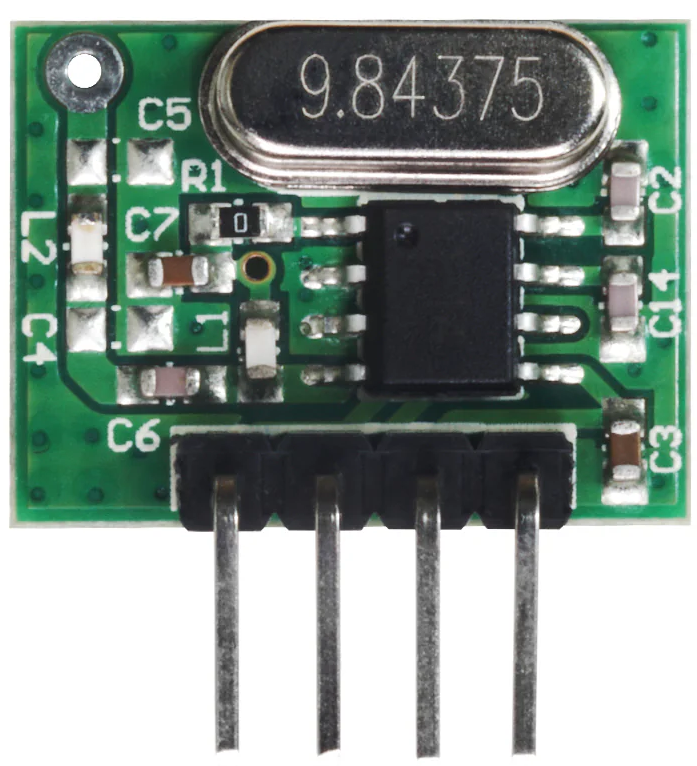
The WL102-341 is a wireless transceiver module designed for low-power communication in Internet of Things (IoT) applications. Its compact design and support for multiple frequency bands make it an ideal choice for reliable data transmission in a variety of environments. This module is widely used in smart home devices, industrial automation, environmental monitoring, and other IoT-based systems where efficient and stable wireless communication is essential.
Explore Projects Built with WL102-341
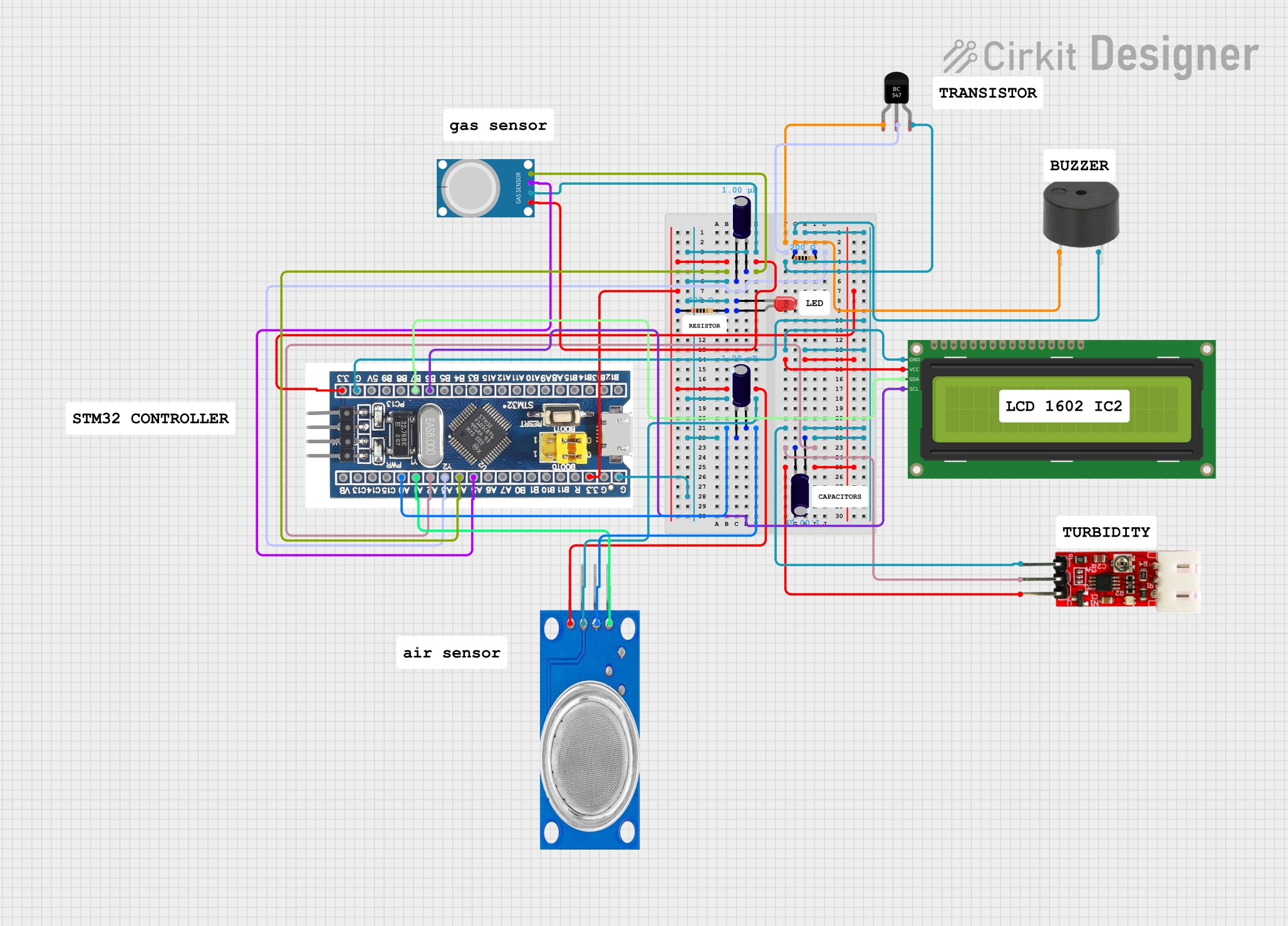


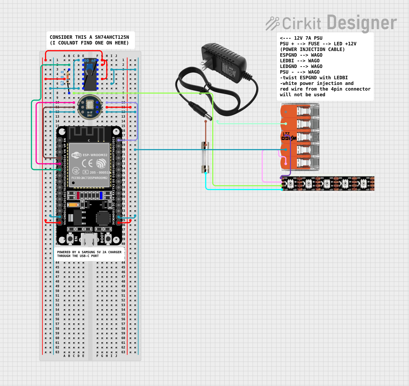
Explore Projects Built with WL102-341
Common Applications:
- Smart home devices (e.g., smart thermostats, lighting systems)
- Industrial automation and control systems
- Environmental monitoring (e.g., weather stations, air quality sensors)
- Wearable devices and health monitoring systems
- Wireless sensor networks
Technical Specifications
The WL102-341 module is engineered to deliver high performance while maintaining low power consumption. Below are its key technical specifications:
| Parameter | Value |
|---|---|
| Operating Voltage | 1.8V to 3.6V |
| Frequency Bands | 433 MHz, 868 MHz, 915 MHz |
| Data Rate | Up to 250 kbps |
| Transmit Power | Up to +10 dBm |
| Sensitivity | -120 dBm |
| Communication Protocol | SPI |
| Operating Temperature | -40°C to +85°C |
| Dimensions | 15mm x 15mm x 2mm |
| Current Consumption | 15 mA (transmit), 10 mA (receive) |
Pin Configuration and Descriptions
The WL102-341 module has 8 pins, each serving a specific function. The table below provides details about the pin configuration:
| Pin Number | Pin Name | Description |
|---|---|---|
| 1 | VCC | Power supply input (1.8V to 3.6V) |
| 2 | GND | Ground connection |
| 3 | SCK | SPI clock input |
| 4 | MOSI | SPI data input (Master Out, Slave In) |
| 5 | MISO | SPI data output (Master In, Slave Out) |
| 6 | CS | Chip select (active low) |
| 7 | IRQ | Interrupt request output |
| 8 | ANT | Antenna connection for wireless communication |
Usage Instructions
How to Use the WL102-341 in a Circuit
- Power Supply: Connect the VCC pin to a regulated power source (1.8V to 3.6V) and the GND pin to the ground of your circuit.
- SPI Communication: Interface the module with a microcontroller (e.g., Arduino UNO) using the SPI pins (SCK, MOSI, MISO, and CS). Ensure proper configuration of the SPI clock speed and mode.
- Antenna Connection: Attach a suitable antenna to the ANT pin to enable wireless communication. Use an antenna designed for the frequency band you are operating in (e.g., 433 MHz, 868 MHz, or 915 MHz).
- Interrupt Handling: Connect the IRQ pin to a GPIO pin on your microcontroller to handle interrupts for events like data reception or transmission completion.
Important Considerations and Best Practices
- Power Supply Stability: Use a low-noise voltage regulator to ensure stable power delivery to the module.
- Antenna Placement: Place the antenna away from other components to minimize interference and maximize signal strength.
- Frequency Band Selection: Ensure compliance with local regulations when selecting the operating frequency band.
- SPI Configuration: Match the SPI settings (clock polarity, phase, and speed) between the WL102-341 and your microcontroller.
Example Code for Arduino UNO
Below is an example of how to interface the WL102-341 with an Arduino UNO for basic communication:
#include <SPI.h>

// Define WL102-341 pin connections
#define CS_PIN 10  // Chip select pin
#define IRQ_PIN 2  // Interrupt pin

void setup() {
  // Initialize serial communication for debugging
  Serial.begin(9600);
  Serial.println("Initializing WL102-341...");

  // Configure SPI settings
  SPI.begin();
  pinMode(CS_PIN, OUTPUT);
  digitalWrite(CS_PIN, HIGH); // Set CS pin high (inactive)

  // Configure IRQ pin as input
  pinMode(IRQ_PIN, INPUT);

  // Additional initialization code for WL102-341 can be added here
  Serial.println("WL102-341 initialized successfully.");
}

void loop() {
  // Example: Send data via SPI
  digitalWrite(CS_PIN, LOW); // Select the WL102-341
  SPI.transfer(0xA5);        // Send a test byte (0xA5)
  digitalWrite(CS_PIN, HIGH); // Deselect the WL102-341

  // Check for interrupt signal
  if (digitalRead(IRQ_PIN) == HIGH) {
    Serial.println("Data received or event triggered.");
  }

  delay(1000); // Wait for 1 second
}
Troubleshooting and FAQs
Common Issues and Solutions
No Communication with the Module
- Cause: Incorrect SPI configuration or wiring.
- Solution: Double-check the SPI settings (clock speed, polarity, and phase) and ensure proper connections between the microcontroller and the WL102-341.
Weak or No Wireless Signal
- Cause: Poor antenna placement or incorrect antenna type.
- Solution: Use an antenna designed for the operating frequency band and place it away from other components or sources of interference.
High Power Consumption
- Cause: Module operating in continuous transmit mode.
- Solution: Use low-power modes when the module is idle and ensure proper configuration of the transmit/receive cycle.
Module Overheating
- Cause: Exceeding the maximum operating voltage or prolonged high-power transmission.
- Solution: Ensure the power supply voltage is within the specified range and limit the transmission power if possible.
FAQs
Q: Can the WL102-341 operate in multiple frequency bands simultaneously?
A: No, the module can only operate in one frequency band at a time. You must configure the desired band during initialization.Q: Is the WL102-341 compatible with 5V microcontrollers?
A: Yes, but you will need a level shifter to step down the 5V logic signals to 3.3V for the module.Q: What is the maximum communication range of the WL102-341?
A: The range depends on the operating frequency, antenna type, and environmental conditions. Typically, it can achieve up to 500 meters in open space.
By following this documentation, you can effectively integrate the WL102-341 into your IoT projects and ensure reliable wireless communication.