How to Use Sensor SHT113 Flame: Examples, Pinouts, and Specs
Introduction
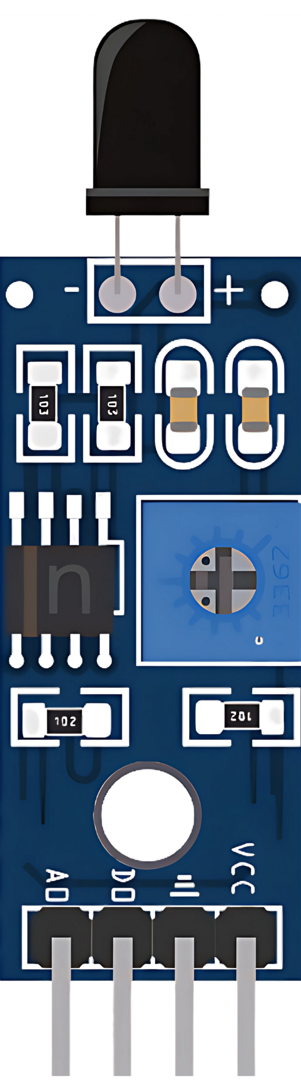
The SHT113 Flame Sensor is an electronic device designed to detect the presence of fire or other sources of heat. It is commonly used in safety systems for homes, offices, and industrial environments to trigger alarms or other safety measures when flames are detected. The sensor operates by detecting infrared (IR) radiation typically emitted by flames, allowing for quick and reliable fire detection.
Explore Projects Built with Sensor SHT113 Flame
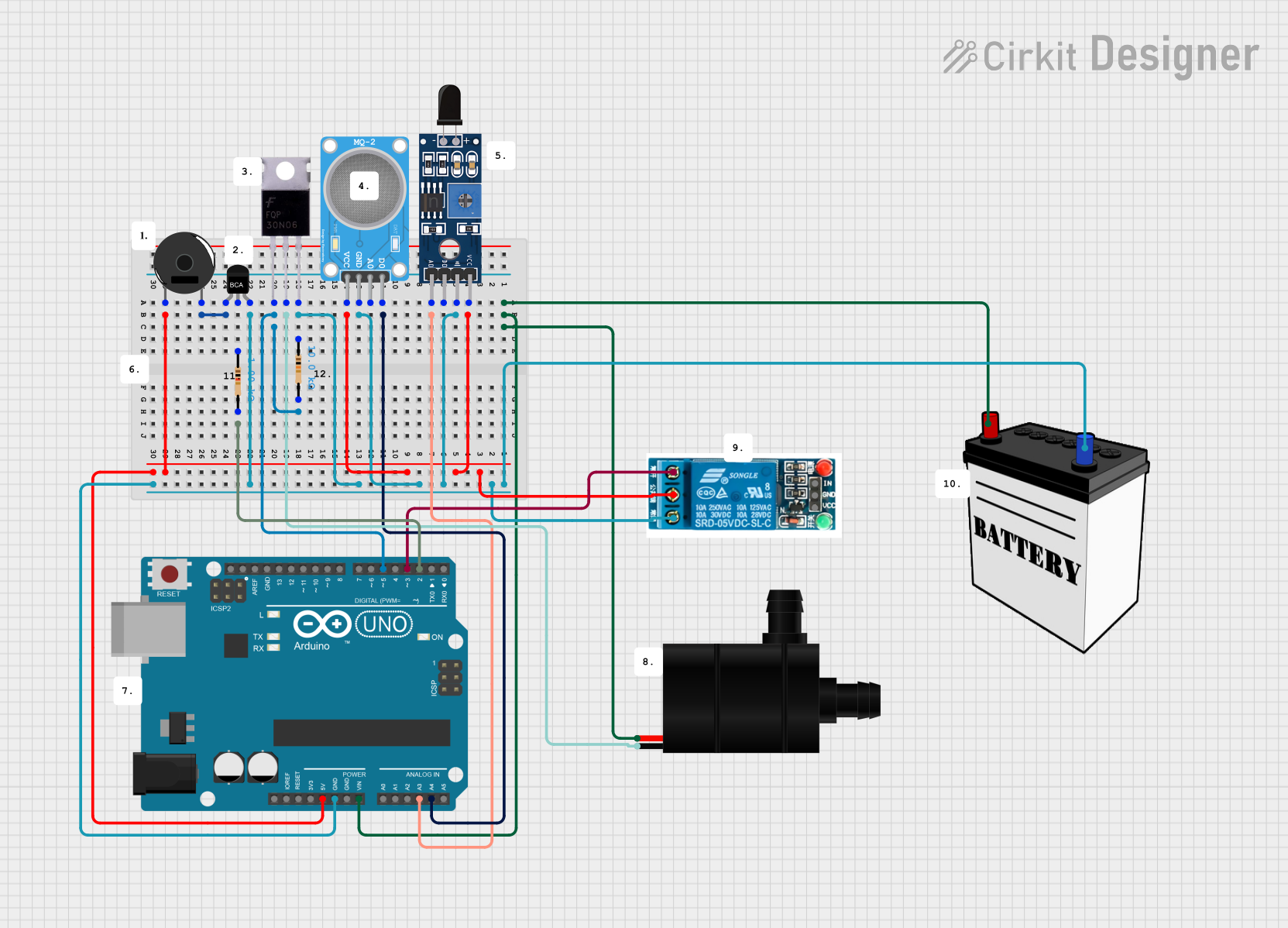
Explore Projects Built with Sensor SHT113 Flame
Common Applications and Use Cases
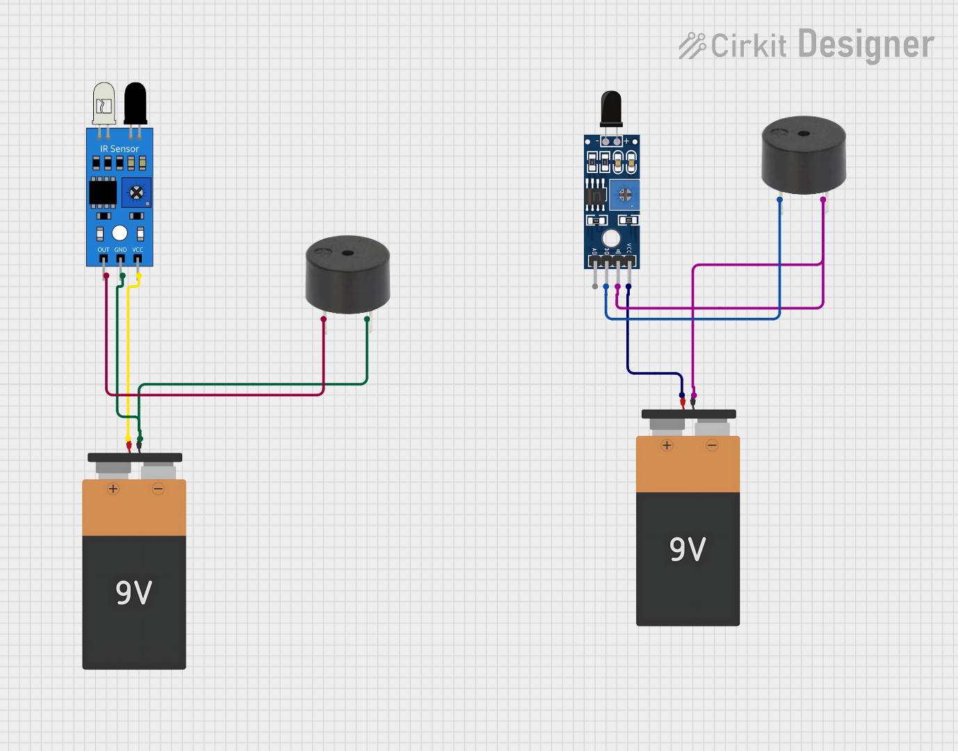
- Fire alarms
- Firefighting robots
- Flame monitoring systems in industrial settings
- Safety systems for gas-powered appliances
Technical Specifications
Key Technical Details
- Operating Voltage: 3.3V to 5V DC
- Output Type: Digital and Analog
- Sensitivity: Adjustable via onboard potentiometer
- Detection Angle: Approximately 60 degrees
- Detection Distance: Up to 100cm (depending on the flame size and sensitivity setting)
Pin Configuration and Descriptions
| Pin Number | Pin Name | Description |
|---|---|---|
| 1 | VCC | Power supply (3.3V to 5V DC) |
| 2 | GND | Ground |
| 3 | D0 | Digital output (0 or 1) |
| 4 | A0 | Analog output (0V to VCC, proportional to flame intensity) |
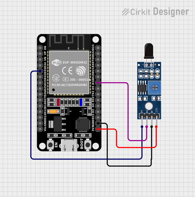
Usage Instructions
How to Use the Component in a Circuit
- Connect the VCC pin to the power supply (3.3V to 5V).
- Connect the GND pin to the ground of the power supply.
- Connect the D0 pin to a digital input pin on a microcontroller if you wish to use the digital output.
- Connect the A0 pin to an analog input pin on a microcontroller if you wish to use the analog output.
Important Considerations and Best Practices
- Ensure that the sensor is placed away from direct sunlight or other IR sources to avoid false alarms.
- Adjust the sensitivity using the onboard potentiometer to suit the specific application.
- Use a pull-up or pull-down resistor on the digital output if required by the microcontroller.
- Test the sensor with actual flames to calibrate the sensitivity properly.
Example Code for Arduino UNO
// Define the digital and analog pins connected to the sensor
const int flameSensorDigitalPin = 2;
const int flameSensorAnalogPin = A0;

void setup() {
  pinMode(flameSensorDigitalPin, INPUT);
  Serial.begin(9600);
}

void loop() {
  int flameDetected = digitalRead(flameSensorDigitalPin);
  int flameIntensity = analogRead(flameSensorAnalogPin);

  if (flameDetected == LOW) { // Assuming active-low signal
    Serial.println("Flame detected!");
  } else {
    Serial.println("No flame detected.");
  }

  // Print the flame intensity value
  Serial.print("Flame intensity: ");
  Serial.println(flameIntensity);

  delay(500); // Delay for half a second
}
Troubleshooting and FAQs
Common Issues Users Might Face
- False Alarms: Adjust the sensitivity potentiometer to reduce false positives.
- No Response: Ensure that the sensor is connected correctly and that the power supply is within the specified voltage range.
- Inconsistent Readings: Avoid placing the sensor in environments with rapid temperature changes or near other sources of IR radiation.
Solutions and Tips for Troubleshooting
- Double-check wiring and connections.
- Use a multimeter to verify the power supply voltage.
- Test the sensor output with a simple LED circuit before connecting it to a microcontroller.
- Replace the sensor if it appears to be damaged or non-functional after testing.
FAQs
Q: Can the SHT113 Flame Sensor detect smoke? A: No, the sensor is designed to detect IR radiation from flames, not smoke particles.
Q: What is the maximum detection distance of the sensor? A: The maximum detection distance can be up to 100cm, but it depends on the flame size and the sensitivity setting.
Q: How do I adjust the sensitivity of the sensor? A: Turn the onboard potentiometer clockwise or counterclockwise to increase or decrease the sensitivity, respectively.
Q: Can the sensor differentiate between different types of flames? A: The sensor does not differentiate between flame types; it detects the presence of IR radiation characteristic of flames.
Remember, this documentation is a starting point for using the SHT113 Flame Sensor. Always conduct thorough testing in the intended application environment to ensure proper operation and safety.