
How to Use Real Time Clock Module - DS1307 RTC Breakout Board: Examples, Pinouts, and Specs
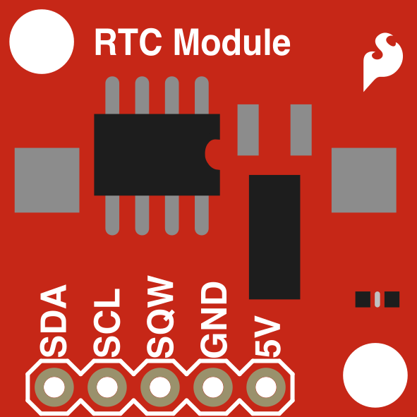
 Design with Real Time Clock Module - DS1307 RTC Breakout Board in Cirkit Designer
Introduction
The DS1307 RTC Breakout Board (Manufacturer: SparkFun, Part ID: BOB-12708) is a real-time clock (RTC) module designed to provide accurate timekeeping for electronic projects. It uses the DS1307 IC to track seconds, minutes, hours, day, date, month, and year, with automatic leap year compensation. The module communicates via the I2C protocol, making it easy to integrate with microcontrollers like Arduino. Additionally, it features a battery backup, ensuring that the time is maintained even during power outages.
Explore Projects Built with Real Time Clock Module - DS1307 RTC Breakout Board
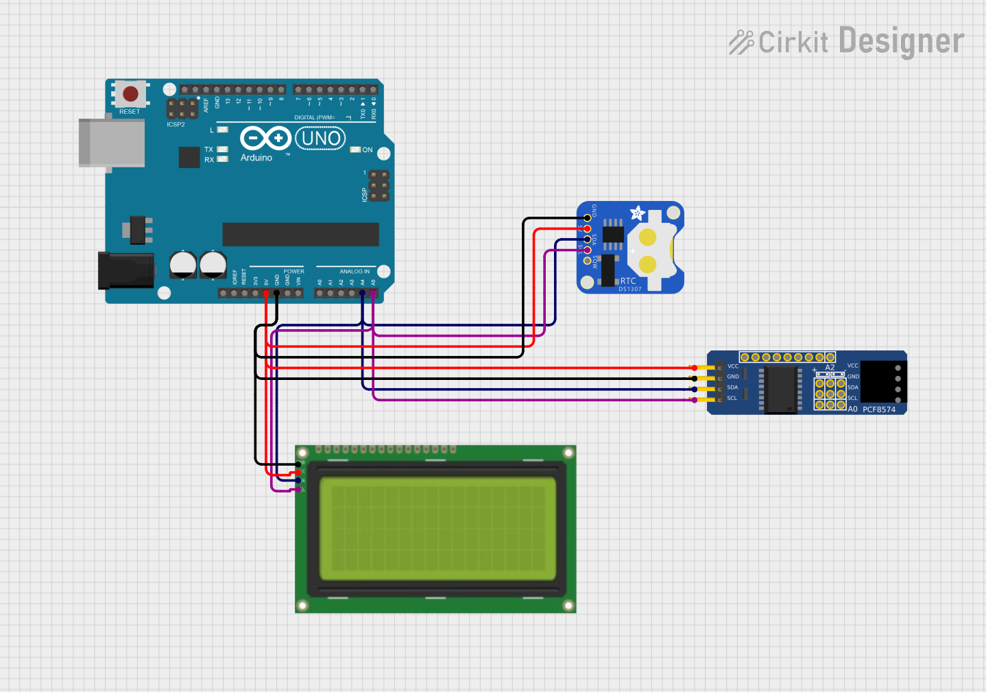 Open Project in Cirkit Designer
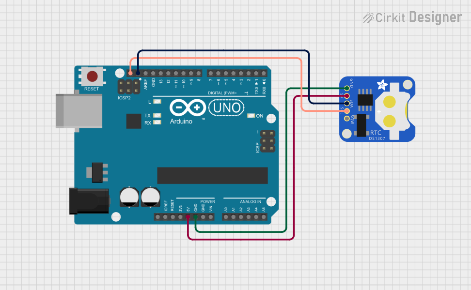 Open Project in Cirkit Designer
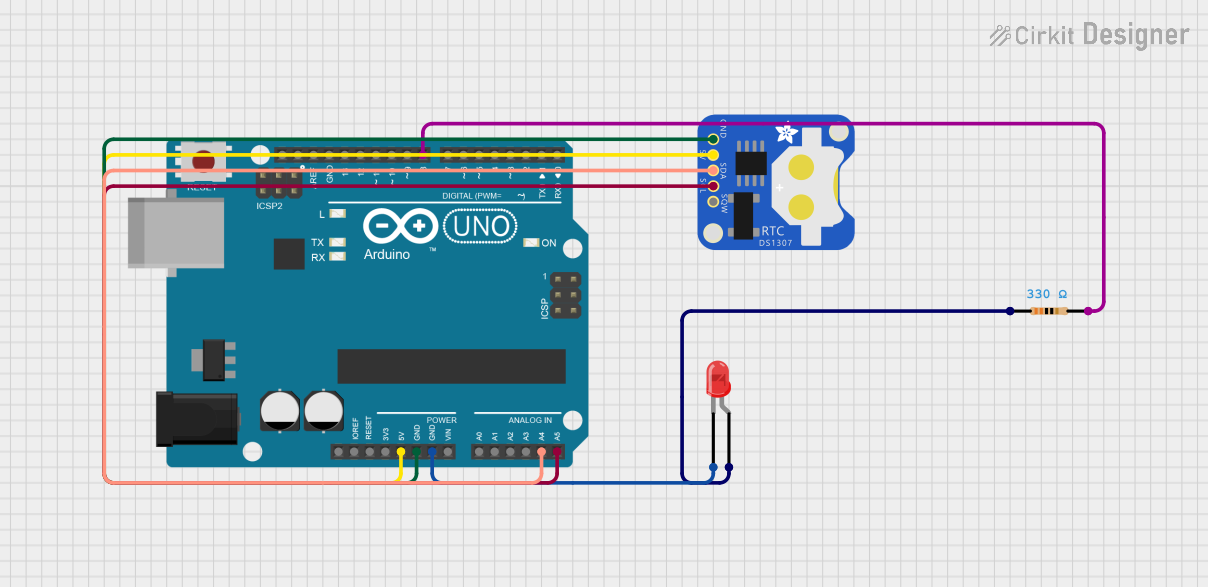 Open Project in Cirkit Designer
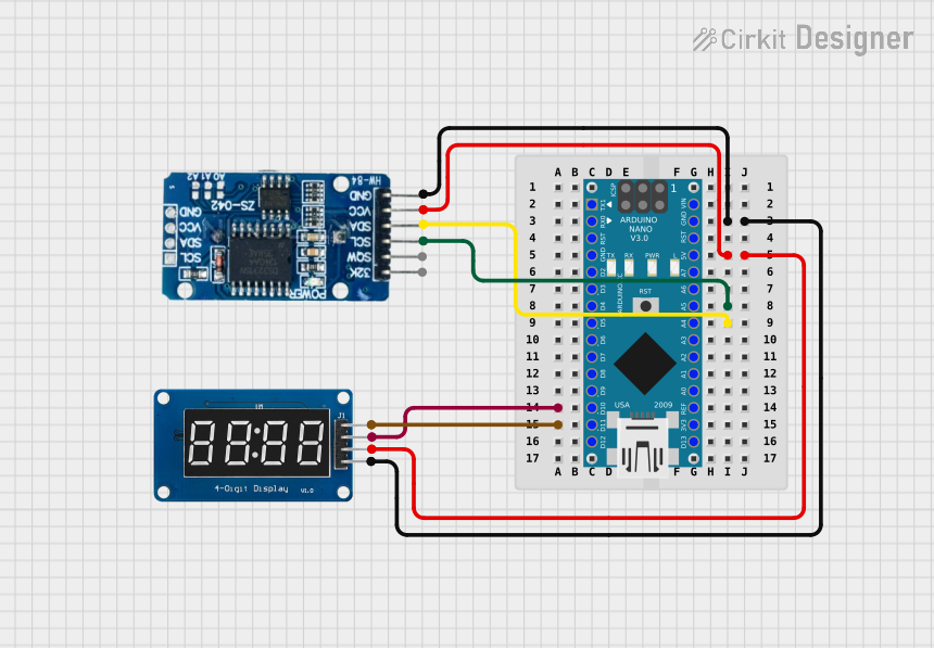 Open Project in Cirkit Designer
Explore Projects Built with Real Time Clock Module - DS1307 RTC Breakout Board
Open Project in Cirkit DesignerOpen Project in Cirkit DesignerOpen Project in Cirkit DesignerOpen Project in Cirkit DesignerCommon Applications
- Data logging systems
- Alarm clocks
- Time-stamped data collection
- Home automation systems
- Scheduling and timing applications
Technical Specifications
The following table outlines the key technical details of the DS1307 RTC Breakout Board:
| Parameter | Specification |
|---|---|
| Operating Voltage | 5V DC |
| Communication Protocol | I2C (Inter-Integrated Circuit) |
| I2C Address | 0x68 (default) |
| Timekeeping Accuracy | ±2 seconds/day (at 25°C) |
| Backup Battery Support | CR1225 coin cell (not included) |
| Battery Voltage Range | 2.0V to 3.5V |
| Operating Temperature | -40°C to +85°C |
| Dimensions | 25.4mm x 25.4mm (1" x 1") |
Pin Configuration
The DS1307 RTC Breakout Board has the following pinout:
| Pin | Name | Description |
|---|---|---|
| 1 | GND | Ground connection |
| 2 | VCC | Power supply input (5V DC) |
| 3 | SDA | Serial Data Line for I2C communication |
| 4 | SCL | Serial Clock Line for I2C communication |
| 5 | SQW | Square Wave Output (optional, programmable frequency: 1Hz, 4kHz, 8kHz, 32kHz) |
Usage Instructions
Connecting the DS1307 RTC Breakout Board
- Power Supply: Connect the
VCCpin to a 5V power source and theGNDpin to ground. - I2C Communication: Connect the
SDAandSCLpins to the corresponding I2C pins on your microcontroller:- For Arduino UNO:
SDA→ A4SCL→ A5
- For Arduino UNO:
- Optional Square Wave Output: If needed, connect the
SQWpin to an input pin on your microcontroller to use the square wave output.
Arduino Example Code
Below is an example of how to use the DS1307 RTC Breakout Board with an Arduino UNO. This code uses the popular RTClib library, which simplifies communication with the DS1307.
#include <Wire.h>
#include <RTClib.h>

// Create an RTC_DS1307 object to interact with the DS1307 module
RTC_DS1307 rtc;

void setup() {
  Serial.begin(9600); // Initialize serial communication for debugging
  Wire.begin();       // Initialize I2C communication

  // Check if the RTC is connected and working
  if (!rtc.begin()) {
    Serial.println("Couldn't find RTC. Check connections!");
    while (1); // Halt the program if RTC is not found
  }

  // Check if the RTC is running; if not, set the time
  if (!rtc.isrunning()) {
    Serial.println("RTC is NOT running, setting the time...");
    rtc.adjust(DateTime(F(__DATE__), F(__TIME__)));
    // Sets the RTC to the date & time of the sketch compilation
  }
}

void loop() {
  // Get the current date and time from the RTC
  DateTime now = rtc.now();

  // Print the current time to the Serial Monitor
  Serial.print(now.year(), DEC);
  Serial.print('/');
  Serial.print(now.month(), DEC);
  Serial.print('/');
  Serial.print(now.day(), DEC);
  Serial.print(" ");
  Serial.print(now.hour(), DEC);
  Serial.print(':');
  Serial.print(now.minute(), DEC);
  Serial.print(':');
  Serial.print(now.second(), DEC);
  Serial.println();

  delay(1000); // Wait for 1 second before updating the time
}
Important Considerations
- Battery Backup: Ensure a CR1225 coin cell battery is installed to maintain timekeeping during power loss.
- I2C Address Conflicts: The DS1307 uses the fixed I2C address
0x68. Ensure no other devices on the I2C bus share this address. - Pull-Up Resistors: The breakout board includes pull-up resistors for the I2C lines. If your circuit already has pull-up resistors, you may need to remove them from the board.
Troubleshooting and FAQs
Common Issues
RTC Not Detected
- Cause: Incorrect wiring or I2C address conflict.
- Solution: Double-check the connections and ensure the I2C address
0x68is not used by another device.
Time Not Updating
- Cause: RTC is not running or the battery is depleted.
- Solution: Use the
rtc.isrunning()function to check if the RTC is running. Replace the battery if necessary.
Incorrect Time
- Cause: RTC was not initialized or set correctly.
- Solution: Use the
rtc.adjust()function to set the correct time.
Square Wave Output Not Working
- Cause: SQW pin not configured or connected.
- Solution: Use the appropriate library functions to configure the square wave output frequency.
FAQs
Q: Can the DS1307 RTC Breakout Board work with 3.3V systems?
A: No, the DS1307 requires a 5V power supply. However, the I2C lines are 5V tolerant, so it can communicate with 3.3V microcontrollers.
Q: How long does the battery last?
A: A typical CR1225 coin cell battery can last several years, depending on usage and environmental conditions.
Q: Can I use the DS1307 for millisecond-level precision?
A: No, the DS1307 is designed for second-level precision. For higher precision, consider using the DS3231 RTC module.
Q: Is the DS1307 affected by daylight saving time?
A: No, the DS1307 does not account for daylight saving time. You must handle this in your code.
This concludes the documentation for the DS1307 RTC Breakout Board. For further assistance, refer to the SparkFun product page or the RTClib library documentation.