How to Use JST SM Male Connector 4 Pin: Examples, Pinouts, and Specs
Introduction
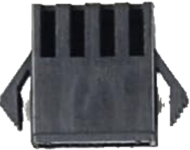
The JST SM Male Connector 4 Pin is a versatile and reliable connector commonly used in various electronic projects. Manufactured by Generic, this connector is designed to provide a secure and stable connection for wires, making it ideal for applications that require robust and durable connections. It is widely used in LED lighting systems, RC vehicles, and other electronic devices where a dependable connection is crucial.
Explore Projects Built with JST SM Male Connector 4 Pin


Explore Projects Built with JST SM Male Connector 4 Pin
Technical Specifications
Key Technical Details
| Parameter | Specification |
|---|---|
| Manufacturer | Generic |
| Part ID | 4 Pin Connector JST SM Male |
| Number of Pins | 4 |
| Connector Type | Male |
| Contact Material | Copper Alloy |
| Insulation Material | Nylon |
| Current Rating | 3A |
| Voltage Rating | 250V AC/DC |
| Operating Temperature | -25°C to +85°C |
| Wire Gauge | 22-28 AWG |
Pin Configuration and Descriptions
| Pin Number | Description | Color Code (Typical) |
|---|---|---|
| 1 | VCC (Power) | Red |
| 2 | Data Signal 1 | Green |
| 3 | Data Signal 2 | Yellow |
| 4 | Ground (GND) | Black |
Usage Instructions
How to Use the Component in a Circuit
- Identify the Pins: Refer to the pin configuration table to identify the function of each pin.
- Prepare the Wires: Strip the insulation off the ends of the wires you intend to connect.
- Insert the Wires: Insert the stripped ends of the wires into the corresponding pins of the connector.
- Secure the Connection: Ensure that the wires are securely fastened within the connector to prevent any loose connections.
- Connect to Circuit: Connect the other end of the wires to the appropriate points in your circuit.
Important Considerations and Best Practices
- Polarity: Ensure correct polarity when connecting power and ground to avoid damage to your components.
- Wire Gauge: Use wires within the specified gauge range (22-28 AWG) for optimal performance.
- Secure Connections: Double-check that all connections are secure to prevent intermittent connectivity issues.
- Environmental Conditions: Consider the operating temperature range (-25°C to +85°C) to ensure reliable performance in your application.
Troubleshooting and FAQs
Common Issues Users Might Face
- Loose Connections: If the connection is not secure, it may result in intermittent connectivity or complete disconnection.
- Incorrect Polarity: Reversing the power and ground connections can damage the connected components.
- Wire Gauge Mismatch: Using wires outside the specified gauge range can lead to poor connections or damage to the connector.
Solutions and Tips for Troubleshooting
- Check Connections: Ensure that all wires are securely fastened within the connector and that there are no loose connections.
- Verify Polarity: Double-check the polarity of the connections to ensure that power and ground are correctly connected.
- Use Correct Wire Gauge: Use wires within the specified gauge range (22-28 AWG) to ensure a secure and reliable connection.
Example Code for Arduino UNO
If you are using the JST SM Male Connector 4 Pin with an Arduino UNO, here is an example code to read data from a sensor connected via this connector:
// Define pin connections
const int vccPin = 2;    // VCC connected to pin 2
const int dataPin1 = 3;  // Data Signal 1 connected to pin 3
const int dataPin2 = 4;  // Data Signal 2 connected to pin 4
const int gndPin = 5;    // GND connected to pin 5

void setup() {
  // Initialize serial communication
  Serial.begin(9600);

  // Set pin modes
  pinMode(vccPin, OUTPUT);
  pinMode(dataPin1, INPUT);
  pinMode(dataPin2, INPUT);
  pinMode(gndPin, OUTPUT);

  // Set initial states
  digitalWrite(vccPin, HIGH);  // Power on the sensor
  digitalWrite(gndPin, LOW);   // Connect ground
}

void loop() {
  // Read data from the sensor
  int sensorValue1 = digitalRead(dataPin1);
  int sensorValue2 = digitalRead(dataPin2);

  // Print sensor values to the serial monitor
  Serial.print("Sensor Value 1: ");
  Serial.println(sensorValue1);
  Serial.print("Sensor Value 2: ");
  Serial.println(sensorValue2);

  // Add a delay for readability
  delay(1000);
}
This code sets up the Arduino UNO to read data from a sensor connected via the JST SM Male Connector 4 Pin. Ensure that the connections are made according to the pin configuration table provided earlier.
By following this documentation, users can effectively utilize the JST SM Male Connector 4 Pin in their electronic projects, ensuring secure and reliable connections.