
How to Use 60mm 8x8 dot matrix column cathode led display with narrow pcb pads: Examples, Pinouts, and Specs
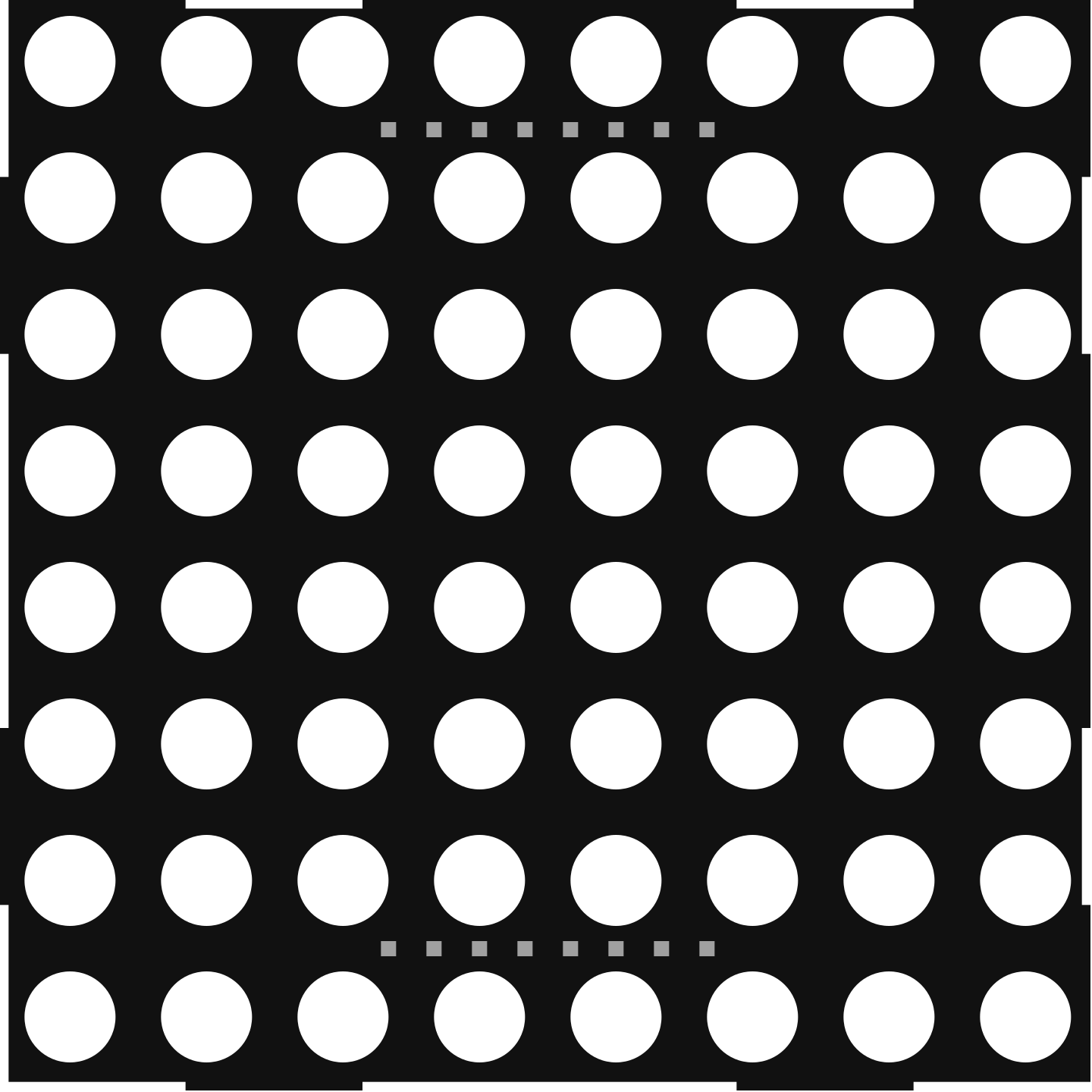
 Design with 60mm 8x8 dot matrix column cathode led display with narrow pcb pads in Cirkit Designer
Introduction
The 60mm x 60mm 8x8 Dot Matrix Column Cathode LED Display is a versatile electronic component designed for visual output. It consists of 64 LEDs arranged in an 8x8 matrix, where each column shares a cathode connection. This design allows for efficient control of individual LEDs using multiplexing techniques. The narrow PCB pads make it easy to integrate into compact circuit designs.
Explore Projects Built with 60mm 8x8 dot matrix column cathode led display with narrow pcb pads
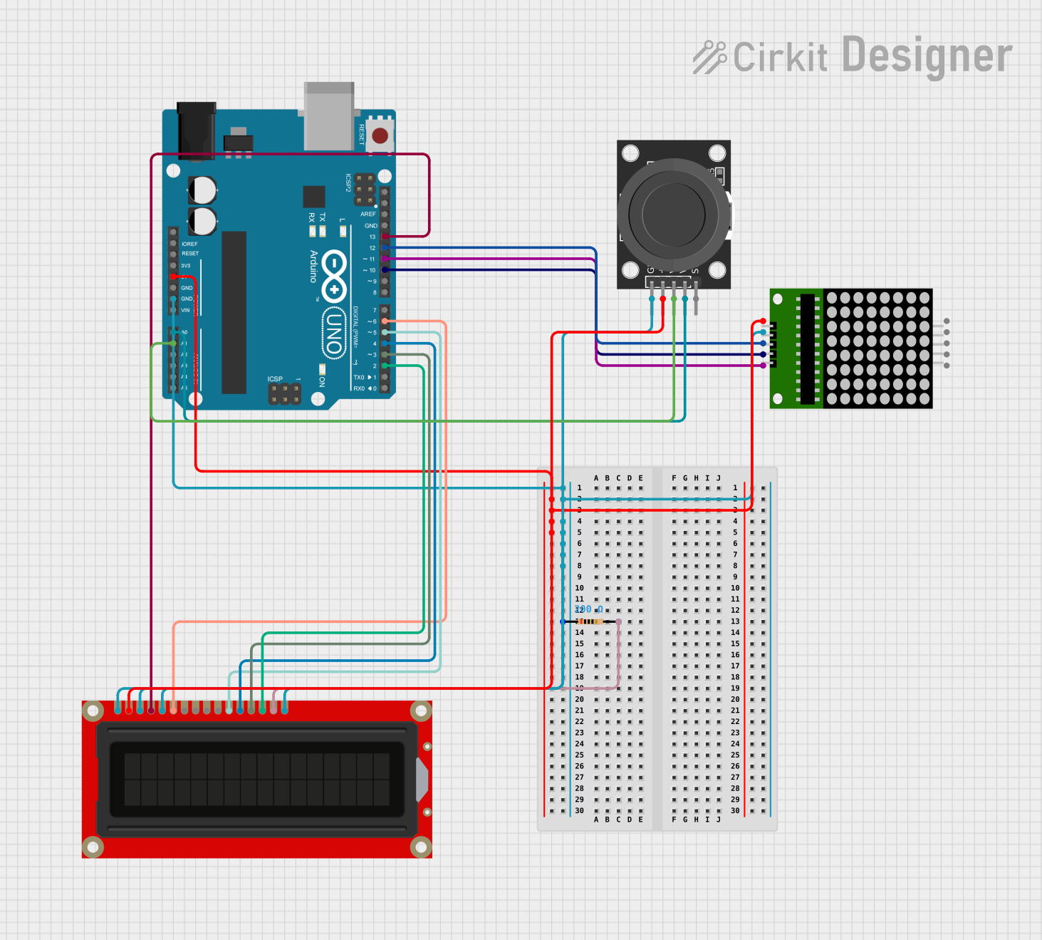 Open Project in Cirkit Designer
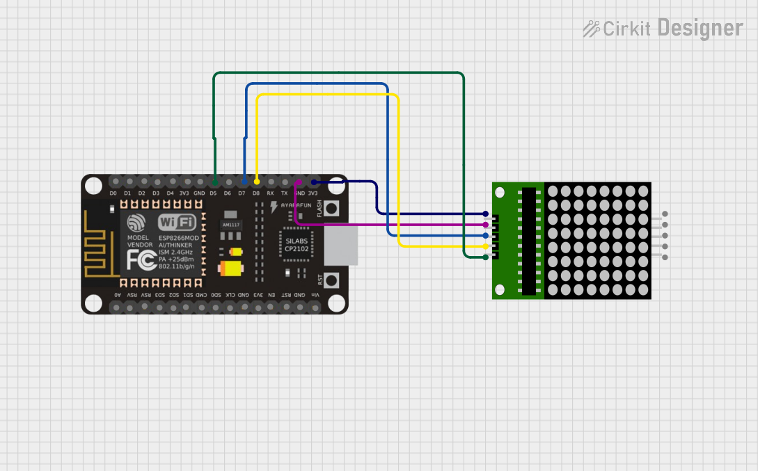 Open Project in Cirkit Designer
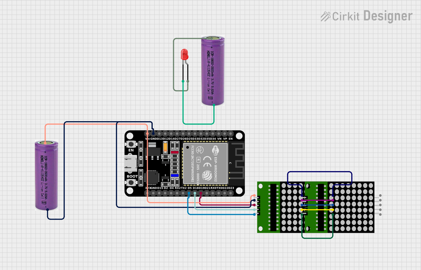 Open Project in Cirkit Designer
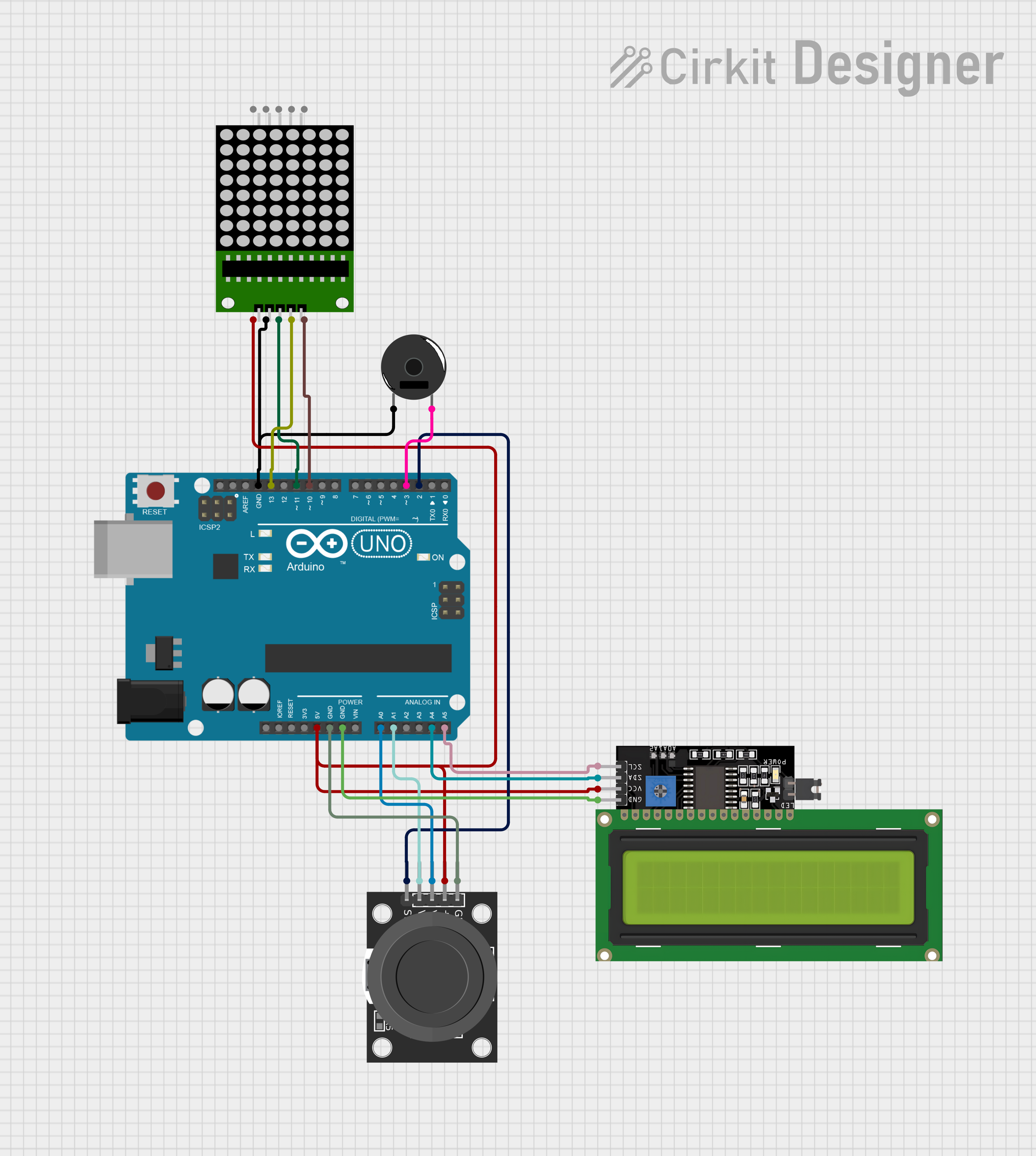 Open Project in Cirkit Designer
Explore Projects Built with 60mm 8x8 dot matrix column cathode led display with narrow pcb pads
Open Project in Cirkit DesignerOpen Project in Cirkit DesignerOpen Project in Cirkit DesignerOpen Project in Cirkit DesignerCommon Applications and Use Cases
- Digital clocks and timers
- Scrolling text displays
- Graphical indicators
- Game displays (e.g., Tetris or Snake)
- Educational projects and prototyping
Technical Specifications
Below are the key technical details of the 60mm 8x8 Dot Matrix Column Cathode LED Display:
| Parameter | Value |
|---|---|
| Dimensions | 60mm x 60mm |
| LED Configuration | 8x8 matrix |
| LED Type | Red (or other colors, depending on model) |
| Forward Voltage (per LED) | 1.8V to 2.2V |
| Forward Current (per LED) | 10mA to 20mA |
| Maximum Reverse Voltage | 5V |
| PCB Pad Type | Narrow pads for easy soldering |
| Operating Temperature | -25°C to +85°C |
Pin Configuration and Descriptions
The 8x8 matrix has 16 pins: 8 for the rows (anodes) and 8 for the columns (cathodes). Below is the pinout configuration:
| Pin Number | Function | Description |
|---|---|---|
| 1-8 | Row Anodes (R1-R8) | Connect to the positive side of the LEDs in each row |
| 9-16 | Column Cathodes (C1-C8) | Connect to the negative side of the LEDs in each column |
Note: The exact pin numbering may vary depending on the manufacturer. Always refer to the datasheet for your specific model.
Usage Instructions
How to Use the Component in a Circuit
- Power Requirements: Ensure that the forward voltage and current ratings of the LEDs are not exceeded. Use current-limiting resistors (typically 220Ω to 1kΩ) in series with the anodes or cathodes.
- Multiplexing: To control the display, use a microcontroller or driver IC (e.g., MAX7219). Multiplexing involves activating one row or column at a time while controlling the LEDs in that row or column.
- Connections:
- Connect the row pins (R1-R8) to the microcontroller's output pins or driver IC.
- Connect the column pins (C1-C8) to the microcontroller or driver IC, ensuring proper grounding.
Important Considerations and Best Practices
- Current Limiting: Always use resistors to prevent overcurrent, which can damage the LEDs.
- Refresh Rate: When multiplexing, ensure a refresh rate of at least 60Hz to avoid flickering.
- Heat Management: Avoid prolonged operation at maximum current to prevent overheating.
- PCB Pads: The narrow pads require precise soldering. Use a fine-tipped soldering iron for best results.
Example Code for Arduino UNO
Below is an example of how to control the display using an Arduino UNO and a MAX7219 driver IC:
#include <LedControl.h> // Include the LedControl library for MAX7219

// Initialize the LedControl object
// Parameters: DIN pin, CLK pin, LOAD pin, number of devices
LedControl lc = LedControl(12, 11, 10, 1);

void setup() {
  lc.shutdown(0, false); // Wake up the MAX7219
  lc.setIntensity(0, 8); // Set brightness level (0-15)
  lc.clearDisplay(0);    // Clear the display
}

void loop() {
  // Example: Display a diagonal line
  for (int i = 0; i < 8; i++) {
    lc.setLed(0, i, i, true); // Turn on LED at row i, column i
    delay(200);               // Wait 200ms
  }
  delay(1000);                // Pause for 1 second
  lc.clearDisplay(0);         // Clear the display
}
Note: The
LedControllibrary simplifies communication with the MAX7219. Install it via the Arduino Library Manager if not already installed.
Troubleshooting and FAQs
Common Issues and Solutions
LEDs Not Lighting Up:
- Check all connections for loose wires or cold solder joints.
- Verify that the current-limiting resistors are correctly installed.
- Ensure the microcontroller or driver IC is powered and functioning.
Flickering LEDs:
- Increase the refresh rate in your code.
- Check for unstable power supply or insufficient decoupling capacitors.
Dim LEDs:
- Verify that the forward current is within the recommended range.
- Check the resistor values; they may be too high.
Short Circuits:
- Inspect the narrow PCB pads for accidental solder bridges.
- Use a multimeter to test for continuity between unintended connections.
FAQs
Q: Can I use this display without a driver IC?
A: Yes, but it requires manual multiplexing using the microcontroller's GPIO pins. This can be resource-intensive and is not recommended for complex applications.
Q: What is the maximum number of displays I can daisy-chain?
A: When using a MAX7219, you can daisy-chain up to 8 displays. Ensure the power supply can handle the total current draw.
Q: Can I use this display with 3.3V microcontrollers?
A: Yes, but ensure the forward voltage of the LEDs is compatible. You may need to adjust resistor values accordingly.
By following this documentation, you can effectively integrate the 60mm 8x8 Dot Matrix Column Cathode LED Display into your projects.