Cirkit Designer Logo
Cirkit Designer
Your all-in-one circuit design IDE
Home / 
Component Documentation

How to Use SSR-25A: Examples, Pinouts, and Specs

Image of SSR-25A
Cirkit Designer LogoDesign with SSR-25A in Cirkit Designer

Introduction

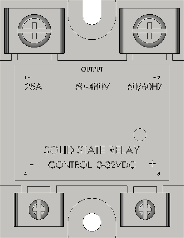
The SSR-25A is a Solid State Relay (SSR) designed to switch and control high-power devices. Unlike mechanical relays, the SSR-25A uses semiconductor devices to switch the load, providing silent, fast, and reliable operation. With a 25A current rating, it is suitable for a wide range of applications including industrial automation, home automation, and temperature control systems.

Explore Projects Built with SSR-25A

Use Cirkit Designer to design, explore, and prototype these projects online. Some projects support real-time simulation. Click "Open Project" to start designing instantly!
Temperature-Controlled Heating System with SSR and Titanium Resistor
Image of Wire Cut Four Slider 33-2 & 33-3 (Old): A project utilizing SSR-25A in a practical application
This circuit is a temperature control system that uses a temperature controller to regulate a heating titanium resistor via a solid-state relay (SSR). The power transformer supplies the necessary voltage to the temperature controller, which in turn controls the SSR to manage the heating element.
Cirkit Designer LogoOpen Project in Cirkit Designer
PID Temperature Control System with Thermocouple and SSR
Image of IR: A project utilizing SSR-25A in a practical application
This circuit is a temperature control system that uses a thermocouple to measure temperature and a PID controller to regulate it. The PID controller drives a solid-state relay (SSR) to control an external load, with power supplied through an AC inlet socket.
Cirkit Designer LogoOpen Project in Cirkit Designer
Satellite-Based Timing and Navigation System with SDR and Atomic Clock Synchronization
Image of GPS 시스템 측정 구성도_Confirm: A project utilizing SSR-25A in a practical application
This circuit appears to be a complex system involving power supply management, GPS and timing synchronization, and data communication. It includes a SI-TEX G1 Satellite Compass for GPS data, an XHTF1021 Atomic Rubidium Clock for precise timing, and Ettus USRP B200 units for software-defined radio communication. Power is supplied through various SMPS units and distributed via terminal blocks and DC jacks. Data communication is facilitated by Beelink MINI S12 N95 computers, RS232 splitters, and a 1000BASE-T Media Converter for network connectivity. RF Directional Couplers are used to interface antennas with the USRP units, and the entire system is likely contained within cases for protection and organization.
Cirkit Designer LogoOpen Project in Cirkit Designer
Arduino-Controlled Multi-Stage Coin-Operated Car Wash System with LCD Display
Image of 4in1: A project utilizing SSR-25A in a practical application
This circuit is a coin-operated control system for a multi-stage process, such as a car wash, managed by an Arduino microcontroller. It includes solid-state relays to control high-power devices, an LCD for user interface, and arcade buttons for user input. The system allows users to insert coins to activate different stages, with settings adjustable via a long-press menu.
Cirkit Designer LogoOpen Project in Cirkit Designer

Explore Projects Built with SSR-25A

Use Cirkit Designer to design, explore, and prototype these projects online. Some projects support real-time simulation. Click "Open Project" to start designing instantly!
Image of Wire Cut Four Slider 33-2 & 33-3 (Old): A project utilizing SSR-25A in a practical application
Temperature-Controlled Heating System with SSR and Titanium Resistor
This circuit is a temperature control system that uses a temperature controller to regulate a heating titanium resistor via a solid-state relay (SSR). The power transformer supplies the necessary voltage to the temperature controller, which in turn controls the SSR to manage the heating element.
Cirkit Designer LogoOpen Project in Cirkit Designer
Image of IR: A project utilizing SSR-25A in a practical application
PID Temperature Control System with Thermocouple and SSR
This circuit is a temperature control system that uses a thermocouple to measure temperature and a PID controller to regulate it. The PID controller drives a solid-state relay (SSR) to control an external load, with power supplied through an AC inlet socket.
Cirkit Designer LogoOpen Project in Cirkit Designer
Image of GPS 시스템 측정 구성도_Confirm: A project utilizing SSR-25A in a practical application
Satellite-Based Timing and Navigation System with SDR and Atomic Clock Synchronization
This circuit appears to be a complex system involving power supply management, GPS and timing synchronization, and data communication. It includes a SI-TEX G1 Satellite Compass for GPS data, an XHTF1021 Atomic Rubidium Clock for precise timing, and Ettus USRP B200 units for software-defined radio communication. Power is supplied through various SMPS units and distributed via terminal blocks and DC jacks. Data communication is facilitated by Beelink MINI S12 N95 computers, RS232 splitters, and a 1000BASE-T Media Converter for network connectivity. RF Directional Couplers are used to interface antennas with the USRP units, and the entire system is likely contained within cases for protection and organization.
Cirkit Designer LogoOpen Project in Cirkit Designer
Image of 4in1: A project utilizing SSR-25A in a practical application
Arduino-Controlled Multi-Stage Coin-Operated Car Wash System with LCD Display
This circuit is a coin-operated control system for a multi-stage process, such as a car wash, managed by an Arduino microcontroller. It includes solid-state relays to control high-power devices, an LCD for user interface, and arcade buttons for user input. The system allows users to insert coins to activate different stages, with settings adjustable via a long-press menu.
Cirkit Designer LogoOpen Project in Cirkit Designer

Technical Specifications

General Features

  • Load Voltage Range: 24-380V AC
  • Control Voltage Range: 3-32V DC
  • Maximum Load Current: 25A
  • Isolation Between Input and Output: >2500V
  • Zero Voltage Turn-On: Minimizes electrical noise during activation
  • Operating Temperature Range: -30°C to +75°C

Pin Configuration and Descriptions

Pin Number Description Notes
1 Control Voltage Input (+) Connect to DC+ of control signal
2 Control Voltage Input (-) Connect to DC- of control signal
3 Load Voltage Output (A1) Connect to AC load
4 Load Voltage Output (A2) Connect to AC line

Usage Instructions

Connecting to a Circuit

  1. Control Signal Connection:

    • Connect the positive side of the DC control signal to Pin 1.
    • Connect the negative side of the DC control signal to Pin 2.
  2. Load Connection:

    • Connect one side of the AC load to Pin 3 (A1).
    • Connect the other side of the AC load to the AC line (A2).

Best Practices

  • Use a heat sink for loads approaching or exceeding 25A to dissipate heat.
  • Ensure proper isolation between the low-voltage control side and the high-voltage load side.
  • Use a snubber circuit if switching highly inductive loads to protect the SSR from voltage spikes.

Example Code for Arduino UNO

// Define the SSR control pin
const int ssrPin = 7;

void setup() {
  // Set the SSR pin as an output
  pinMode(ssrPin, OUTPUT);
}

void loop() {
  // Turn on the SSR for 5 seconds
  digitalWrite(ssrPin, HIGH);
  delay(5000);
  
  // Turn off the SSR for 5 seconds
  digitalWrite(ssrPin, LOW);
  delay(5000);
}

Troubleshooting and FAQs

Common Issues

  • SSR Not Activating: Ensure control voltage is within 3-32V DC range and connections are correct.
  • Overheating: Check if the current rating of the load exceeds the SSR rating or if adequate heat sinking is in place.
  • Load Not Switching: Verify that the load voltage is within the specified range and connections are secure.

FAQs

Q: Can the SSR-25A be used to switch DC loads? A: No, the SSR-25A is designed for AC loads only.

Q: Is there a need for a protective diode across the control input like with mechanical relays? A: No, a protective diode is not necessary as there are no inductive components in the control circuit of the SSR.

Q: How do I know if the SSR is on or off? A: Some SSRs have an LED indicator. If not, measuring the voltage across the load can indicate whether the SSR is conducting.

Q: Can I use PWM to control the SSR? A: Yes, but ensure the frequency is suitable for the SSR and the load. Some SSRs may not switch fast enough for high-frequency PWM.

Remember to always consult the SSR-25A datasheet for specific details and contact technical support if you encounter issues not covered in this documentation.