
How to Use DC Power Supply Module: Examples, Pinouts, and Specs
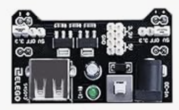
 Design with DC Power Supply Module in Cirkit Designer
Introduction
The DC Power Supply Module is a versatile electronic component designed to convert alternating current (AC) voltage into a stable direct current (DC) voltage. It is widely used in powering electronic circuits, microcontrollers, sensors, and other components that require a reliable DC voltage source. This module is an essential tool for prototyping, testing, and operating electronic devices.
Explore Projects Built with DC Power Supply Module
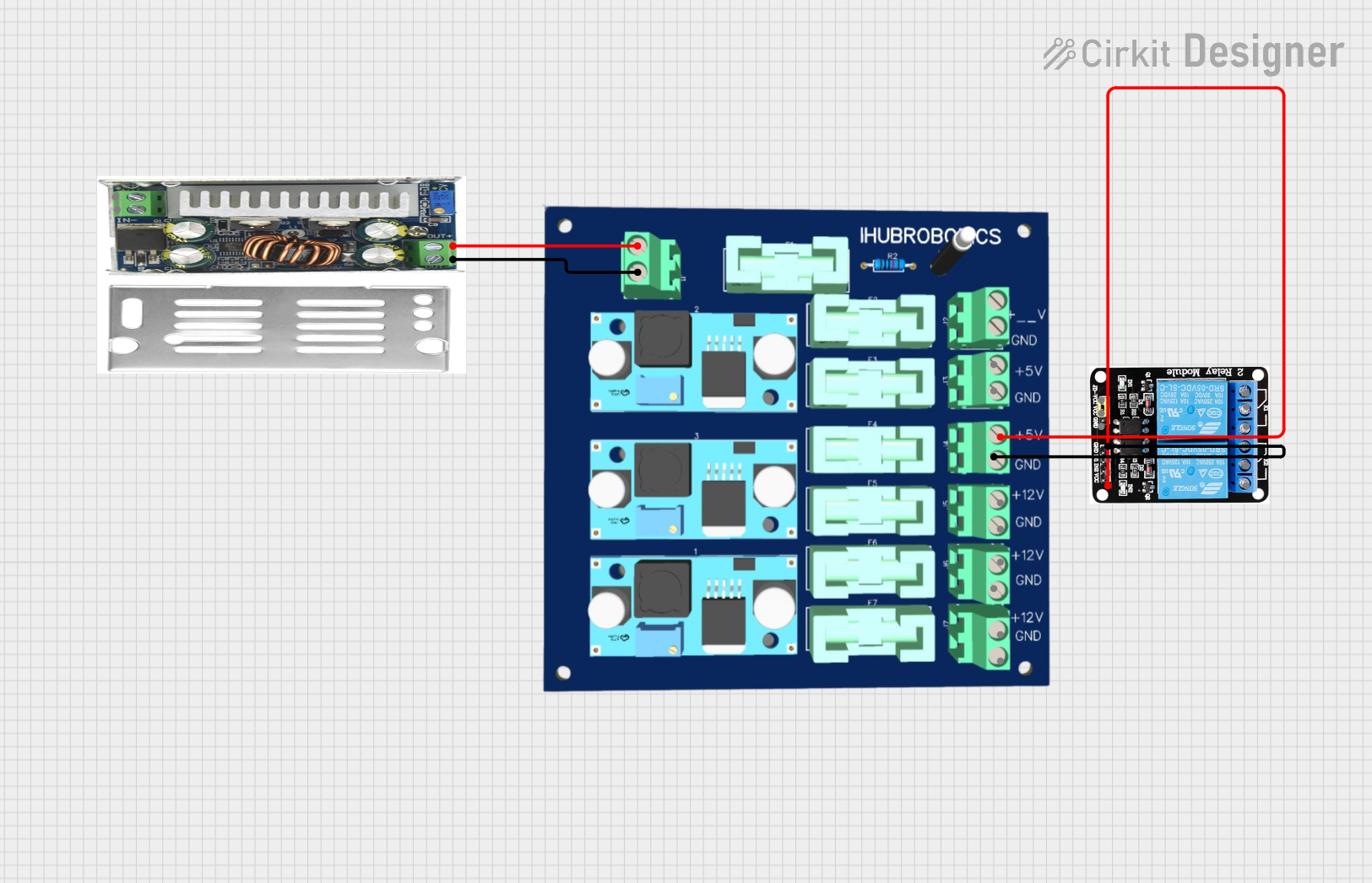 Open Project in Cirkit Designer
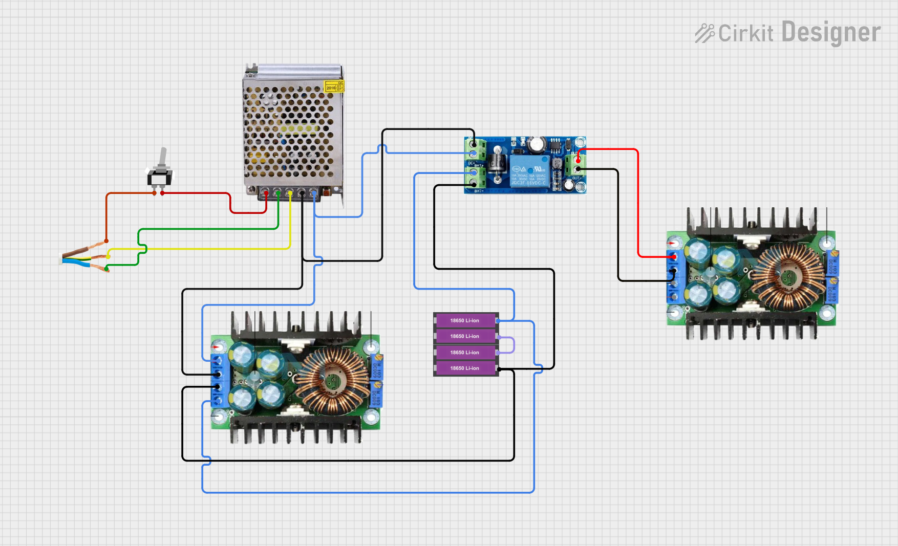 Open Project in Cirkit Designer
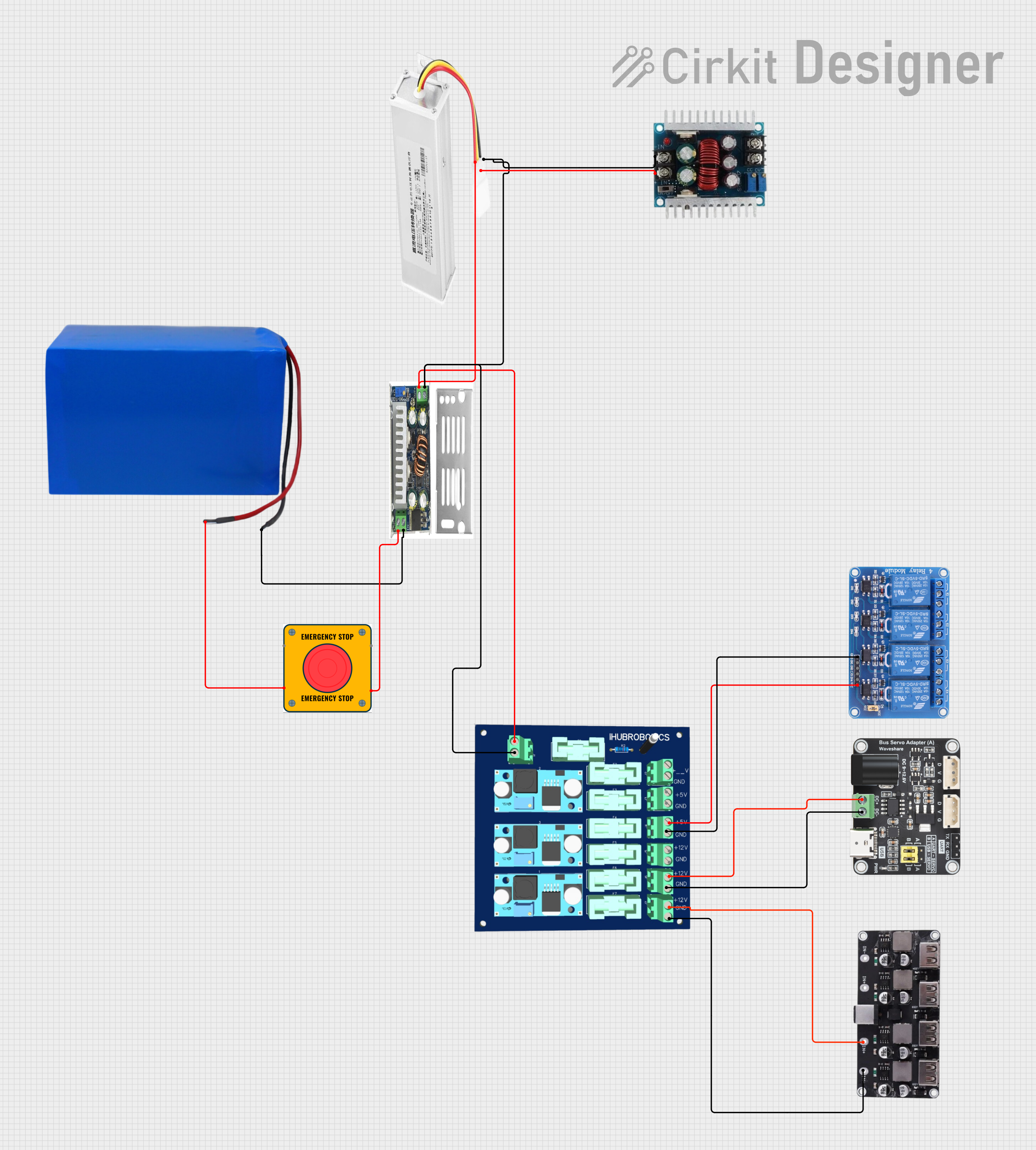 Open Project in Cirkit Designer
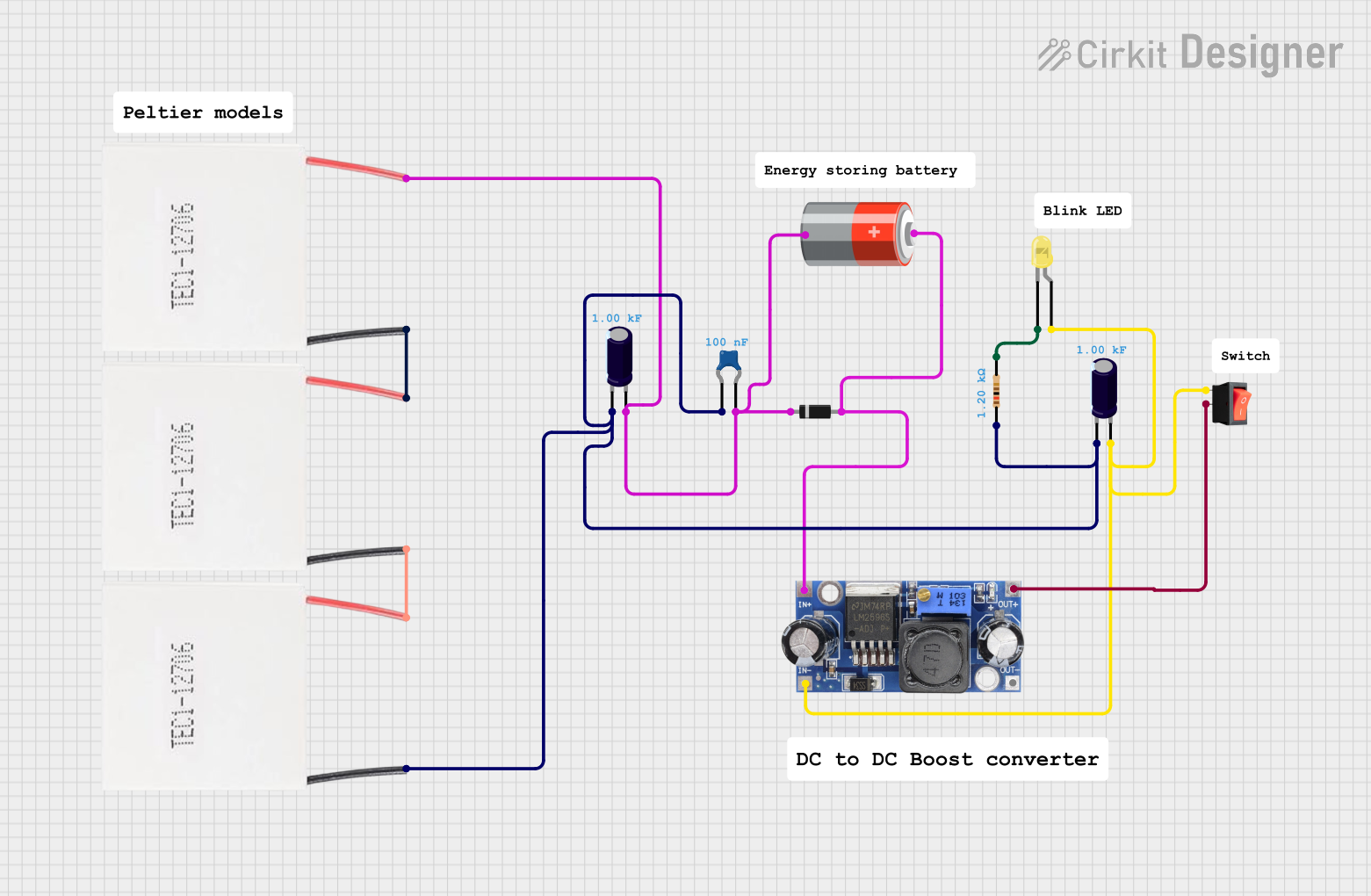 Open Project in Cirkit Designer
Explore Projects Built with DC Power Supply Module
Open Project in Cirkit DesignerOpen Project in Cirkit DesignerOpen Project in Cirkit DesignerOpen Project in Cirkit DesignerCommon Applications and Use Cases
- Powering microcontroller boards (e.g., Arduino, Raspberry Pi)
- Supplying power to sensors, actuators, and modules
- Bench testing and prototyping electronic circuits
- Battery charging applications
- Industrial and consumer electronics
Technical Specifications
Below are the key technical details of a typical DC Power Supply Module:
| Parameter | Specification |
|---|---|
| Input Voltage Range | 100V - 240V AC (50/60 Hz) |
| Output Voltage Range | 3.3V, 5V, 9V, 12V DC (varies by model) |
| Output Current | 1A - 3A (depending on the module) |
| Power Rating | 5W - 36W |
| Efficiency | Up to 85% |
| Ripple Voltage | < 50mV |
| Operating Temperature | -20°C to +70°C |
| Protection Features | Over-voltage, over-current, and short-circuit protection |
Pin Configuration and Descriptions
The DC Power Supply Module typically has the following pins or terminals:
| Pin/Terminal | Description |
|---|---|
| AC Input (L, N) | Connects to the live (L) and neutral (N) AC mains. |
| DC Output (+, -) | Provides the regulated DC voltage output. |
| Ground (GND) | Common ground for the circuit. |
| Adjustment (if available) | Allows fine-tuning of the output voltage. |
Usage Instructions
How to Use the Component in a Circuit
- Connect the AC Input:
- Attach the live (L) and neutral (N) wires from the AC mains to the corresponding input terminals of the module. Ensure proper insulation and safety precautions.
- Set the Output Voltage (if adjustable):
- Use the onboard potentiometer or adjustment screw to set the desired output voltage. Use a multimeter to verify the voltage.
- Connect the DC Output:
- Attach the positive (+) and negative (-) terminals to the load or circuit requiring power.
- Power On:
- Switch on the AC mains supply. The module will convert the AC input to a stable DC output.
Important Considerations and Best Practices
- Safety First: Always handle the AC input connections with care to avoid electric shock. Use insulated tools and ensure the module is properly enclosed.
- Verify Voltage and Current Ratings: Ensure the module's output voltage and current ratings match the requirements of your circuit.
- Heat Dissipation: If the module operates at high power, ensure adequate ventilation or heat sinking to prevent overheating.
- Polarity: Double-check the polarity of the DC output connections to avoid damaging your circuit.
- Testing: Use a multimeter to confirm the output voltage before connecting sensitive components.
Example: Using with an Arduino UNO
To power an Arduino UNO using a DC Power Supply Module:
- Set the module's output voltage to 5V.
- Connect the module's positive (+) output to the Arduino's 5V pin.
- Connect the module's negative (-) output to the Arduino's GND pin.
Alternatively, you can use the barrel jack on the Arduino UNO:
- Set the module's output voltage to 9V.
- Connect the positive (+) output to the center pin of the barrel jack.
- Connect the negative (-) output to the outer sleeve of the barrel jack.
Sample Code for Testing with Arduino
// This code blinks an LED connected to pin 13 of the Arduino UNO.
// Ensure the Arduino is powered by the DC Power Supply Module.

void setup() {
  pinMode(13, OUTPUT); // Set pin 13 as an output pin
}

void loop() {
  digitalWrite(13, HIGH); // Turn the LED on
  delay(1000);            // Wait for 1 second
  digitalWrite(13, LOW);  // Turn the LED off
  delay(1000);            // Wait for 1 second
}
Troubleshooting and FAQs
Common Issues Users Might Face
No Output Voltage:
- Cause: Incorrect AC input connection or blown fuse.
- Solution: Verify the AC input connections and check the fuse. Replace if necessary.
Output Voltage Fluctuations:
- Cause: Overloading the module or insufficient input voltage.
- Solution: Reduce the load or ensure the AC input voltage is within the specified range.
Overheating:
- Cause: Prolonged operation at maximum load or poor ventilation.
- Solution: Reduce the load or improve ventilation around the module.
Circuit Not Powering On:
- Cause: Incorrect polarity or loose connections.
- Solution: Double-check the polarity and ensure all connections are secure.
FAQs
Q1: Can I use this module to charge a battery?
A1: Yes, but ensure the output voltage and current are suitable for the battery type. Use a charge controller for lithium-ion batteries.
Q2: Is the module safe to use with sensitive electronics?
A2: Yes, the module provides a stable DC output with low ripple voltage, making it suitable for sensitive devices.
Q3: Can I adjust the output voltage while the module is powering a circuit?
A3: It is not recommended. Disconnect the load, adjust the voltage, and verify it with a multimeter before reconnecting the load.
Q4: What happens if I exceed the module's current rating?
A4: The module's over-current protection will activate, shutting down the output to prevent damage. Reduce the load and restart the module.