
How to Use DeadOn RTC - DS3234 Breakout: Examples, Pinouts, and Specs
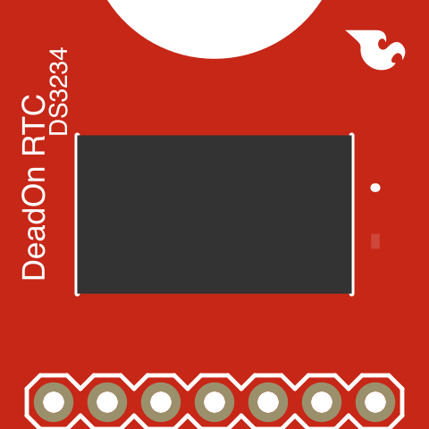
 Design with DeadOn RTC - DS3234 Breakout in Cirkit Designer
Introduction
The DeadOn RTC - DS3234 Breakout (manufacturer part ID: BOB-10160) by SparkFun Electronics is a highly accurate real-time clock (RTC) module based on the DS3234 chip. This module is designed to provide precise timekeeping and includes a battery backup to maintain time even during power outages. It communicates with microcontrollers via the SPI interface, making it suitable for a wide range of applications.
In addition to timekeeping, the DS3234 chip offers advanced features such as programmable alarms, temperature sensing, and a 256-byte SRAM for user data storage. These features make the DeadOn RTC ideal for projects requiring reliable timekeeping and additional functionality.
Explore Projects Built with DeadOn RTC - DS3234 Breakout
 Open Project in Cirkit Designer
 Open Project in Cirkit Designer
 Open Project in Cirkit Designer
 Open Project in Cirkit Designer
Explore Projects Built with DeadOn RTC - DS3234 Breakout
Open Project in Cirkit DesignerOpen Project in Cirkit DesignerOpen Project in Cirkit DesignerOpen Project in Cirkit DesignerCommon Applications
- Data logging systems
- Time-stamped event recording
- Alarm systems
- Industrial automation
- IoT devices requiring precise time synchronization
Technical Specifications
Key Technical Details
| Parameter | Specification |
|---|---|
| Chip | DS3234 |
| Communication Interface | SPI (Serial Peripheral Interface) |
| Operating Voltage | 3.3V to 5.5V |
| Timekeeping Accuracy | ±2 ppm (±0.17 seconds/day) at 0°C to +40°C |
| Battery Backup Voltage | 2.3V to 3.7V (CR1225 coin cell recommended) |
| SRAM | 256 bytes |
| Temperature Sensor Range | -40°C to +85°C |
| Alarm Functions | Two programmable alarms |
| Dimensions | 1.0" x 1.0" (25.4mm x 25.4mm) |
Pin Configuration and Descriptions
The DeadOn RTC breakout board has the following pin layout:
| Pin Name | Pin Type | Description |
|---|---|---|
| VCC | Power Input | Supply voltage (3.3V to 5.5V). |
| GND | Ground | Ground connection. |
| CS | Digital Input | Chip Select for SPI communication. Active LOW. |
| SCK | Digital Input | SPI Clock signal. |
| MOSI | Digital Input | Master Out Slave In (data input to the RTC). |
| MISO | Digital Output | Master In Slave Out (data output from the RTC). |
| INT/SQW | Digital Output | Interrupt or Square Wave output (configurable). |
| 32kHz | Digital Output | 32kHz clock output (optional). |
| RST | Digital Input | Reset pin for the DS3234 chip. Active LOW. |
Usage Instructions
How to Use the DeadOn RTC in a Circuit
- Power Supply: Connect the VCC pin to a 3.3V or 5V power source and the GND pin to ground.
- SPI Communication: Connect the CS, SCK, MOSI, and MISO pins to the corresponding SPI pins on your microcontroller.
- Battery Backup: Insert a CR1225 coin cell battery into the battery holder to maintain timekeeping during power outages.
- Interrupts and Alarms: Use the INT/SQW pin to trigger interrupts or output a square wave signal, as configured in the DS3234 registers.
- Optional Outputs: The 32kHz pin can be used to output a 32kHz clock signal if needed.
Important Considerations and Best Practices
- Ensure the SPI clock speed does not exceed the DS3234's maximum supported frequency (20 MHz).
- Use pull-up resistors on the SPI lines if required by your microcontroller.
- Configure the DS3234 registers carefully to set alarms, enable the square wave output, or access the SRAM.
- Avoid shorting the battery backup terminals to prevent damage to the module.
- For long-term accuracy, consider calibrating the RTC using the temperature compensation feature.
Example Code for Arduino UNO
Below is an example of how to interface the DeadOn RTC with an Arduino UNO using the SPI library:
#include <SPI.h>

// Define SPI pins for the DS3234 RTC
#define CS_PIN 10  // Chip Select pin connected to Arduino pin 10

void setup() {
  Serial.begin(9600);  // Initialize serial communication
  SPI.begin();         // Initialize SPI communication
  pinMode(CS_PIN, OUTPUT);
  digitalWrite(CS_PIN, HIGH);  // Set CS pin HIGH to deselect the RTC

  // Initialize the RTC
  rtcWriteRegister(0x0E, 0x00);  // Disable alarms and square wave output
  Serial.println("RTC Initialized");
}

void loop() {
  // Read the current time from the RTC
  digitalWrite(CS_PIN, LOW);  // Select the RTC
  SPI.transfer(0x00);         // Send address to read seconds register
  byte seconds = SPI.transfer(0x00);  // Read seconds
  digitalWrite(CS_PIN, HIGH); // Deselect the RTC

  // Print the time to the Serial Monitor
  Serial.print("Seconds: ");
  Serial.println(seconds & 0x7F);  // Mask the highest bit (clock halt bit)
  delay(1000);  // Wait for 1 second
}

// Function to write to a DS3234 register
void rtcWriteRegister(byte reg, byte value) {
  digitalWrite(CS_PIN, LOW);  // Select the RTC
  SPI.transfer(reg | 0x80);  // Set the write bit (MSB = 1)
  SPI.transfer(value);       // Write the value to the register
  digitalWrite(CS_PIN, HIGH); // Deselect the RTC
}
Troubleshooting and FAQs
Common Issues and Solutions
RTC Not Responding Over SPI:
- Ensure the CS, SCK, MOSI, and MISO pins are correctly connected.
- Verify that the SPI clock speed is within the DS3234's limits (≤20 MHz).
- Check for loose connections or soldering issues on the breakout board.
Time Resets After Power Loss:
- Confirm that a CR1225 coin cell battery is installed in the battery holder.
- Ensure the battery voltage is within the recommended range (2.3V to 3.7V).
Incorrect Time or Date:
- Verify that the time and date were set correctly in the DS3234 registers.
- Check for software bugs in your code that might overwrite the RTC settings.
Interrupts or Alarms Not Triggering:
- Ensure the INT/SQW pin is connected to the correct interrupt pin on your microcontroller.
- Double-check the alarm configuration in the DS3234 registers.
FAQs
Q: Can the DeadOn RTC operate without a battery?
A: Yes, the RTC will function without a battery as long as it is powered by VCC. However, the time will reset if power is lost.
Q: How accurate is the DS3234 RTC?
A: The DS3234 has an accuracy of ±2 ppm (±0.17 seconds/day) at 0°C to +40°C, making it highly precise for most applications.
Q: Can I use the DeadOn RTC with a 3.3V microcontroller?
A: Yes, the module is compatible with both 3.3V and 5V systems.
Q: What is the purpose of the 256-byte SRAM?
A: The SRAM can be used to store user data that needs to be retained while the RTC is powered.
This concludes the documentation for the DeadOn RTC - DS3234 Breakout. For further assistance, refer to the SparkFun product page or the DS3234 datasheet.