Cirkit Designer
Your all-in-one circuit design IDE
Home /
Component Documentation
How to Use Multimétro: Examples, Pinouts, and Specs

Introduction
A multimeter is a versatile instrument used to measure electrical properties such as voltage, current, and resistance in circuits. It is an essential tool for anyone working with electronics, from hobbyists to professional engineers. Multimeters can be either analog or digital, with digital multimeters (DMMs) being more common due to their higher accuracy and ease of use.
Explore Projects Built with Multimétro
Arduino UNO-Based Sensor Monitoring and GSM Communication System
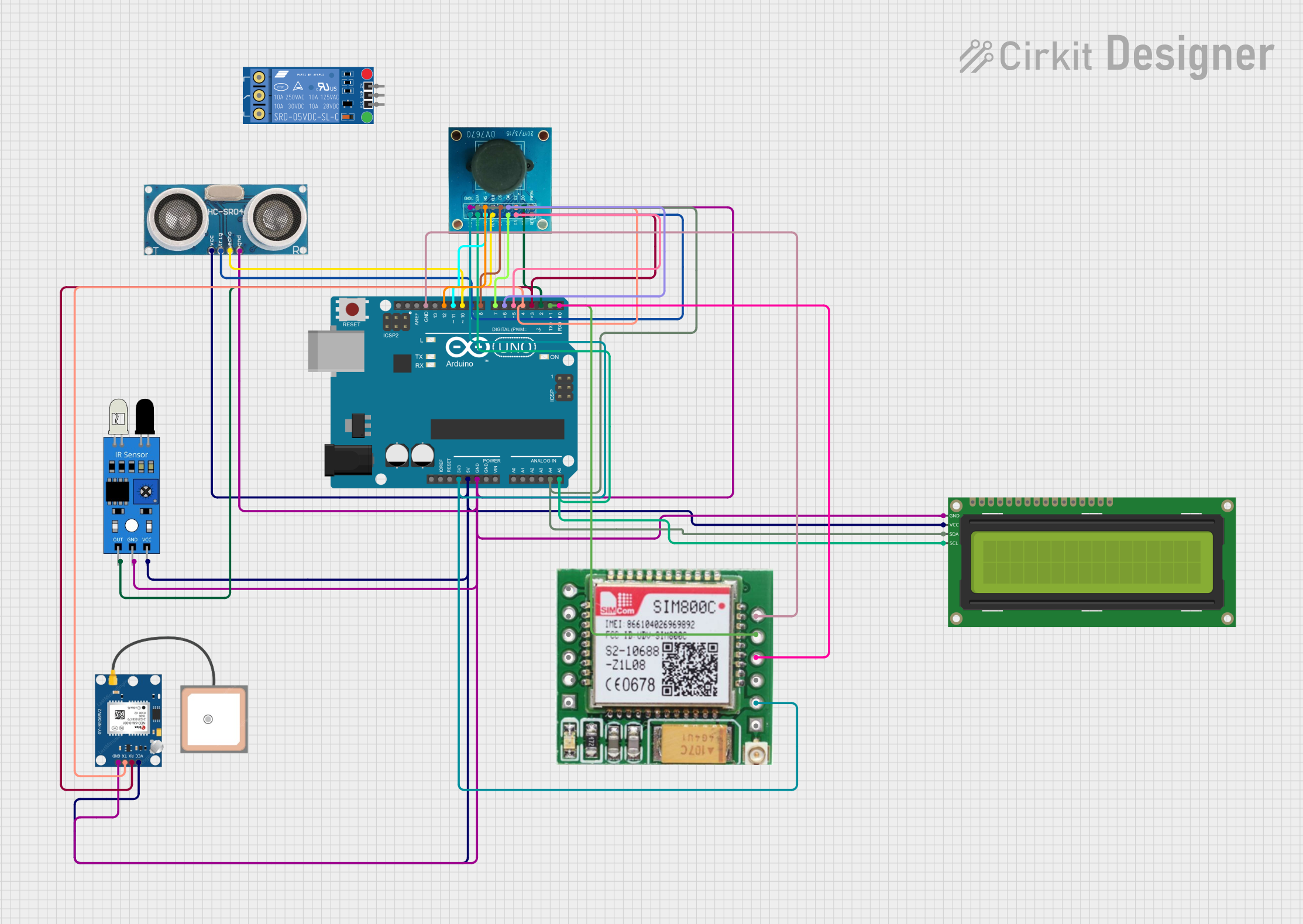
This is a multifunctional Arduino-based system designed to interface with an ultrasonic sensor for distance measurement, an IR sensor for object detection, a GPS module for location tracking, a GSM module for cellular communication, an I2C LCD display for user interface, and an OV7670 camera module for image capture. The Arduino manages sensor data processing and module communication, indicating a complex application such as a security or surveillance device with remote reporting capabilities.
Arduino-Powered Environmental Monitoring Station with OLED Display and Solar Charging
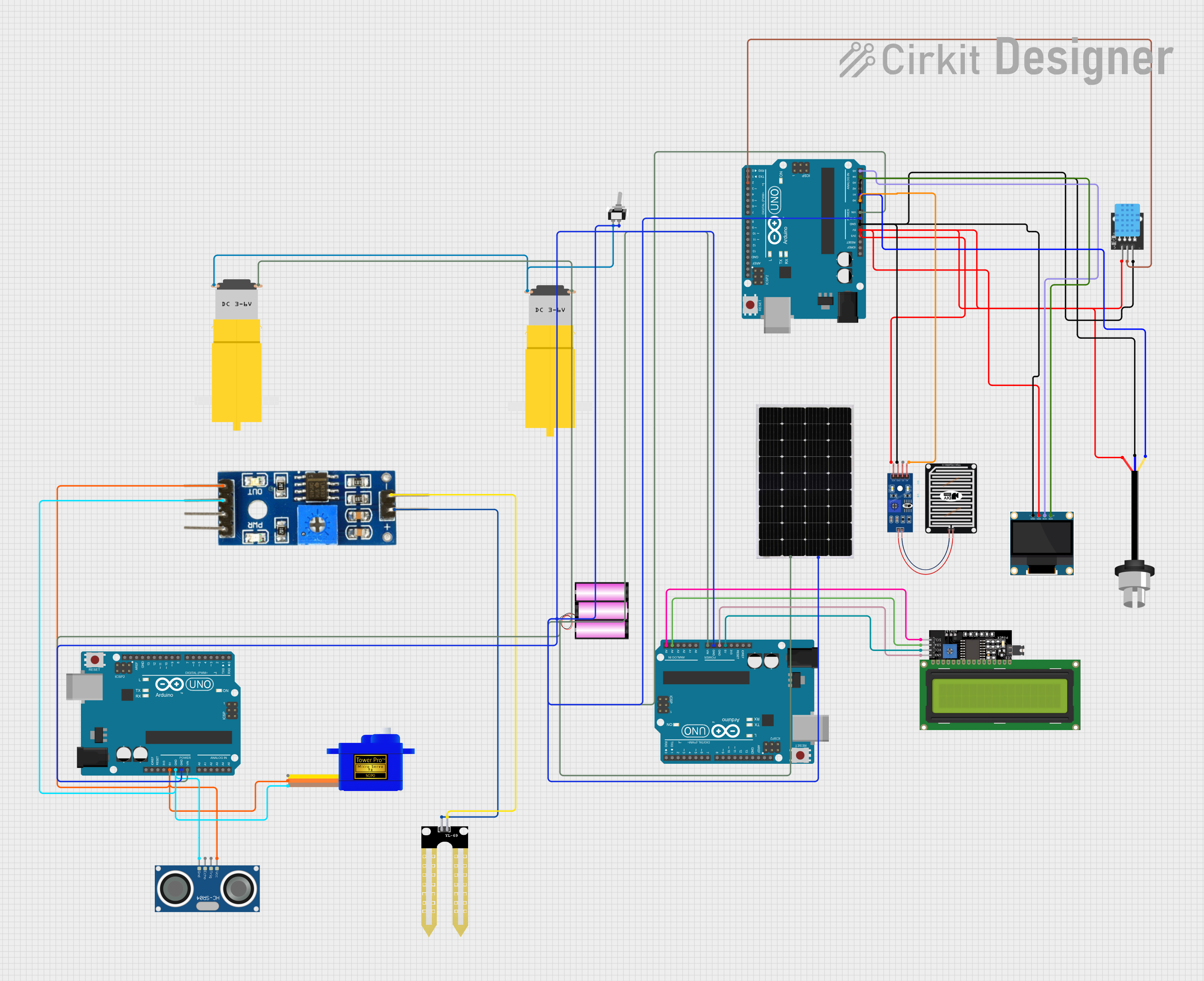
This is a multi-sensor environmental monitoring system with data display capabilities, powered by renewable energy. It collects data from various sensors, displays information on OLED and LCD screens, and includes motor actuators for responsive actions, all controlled by Arduino UNO microcontrollers.
Arduino UNO-Based RFID and Ultrasonic Sensor Security System with LED Indicators
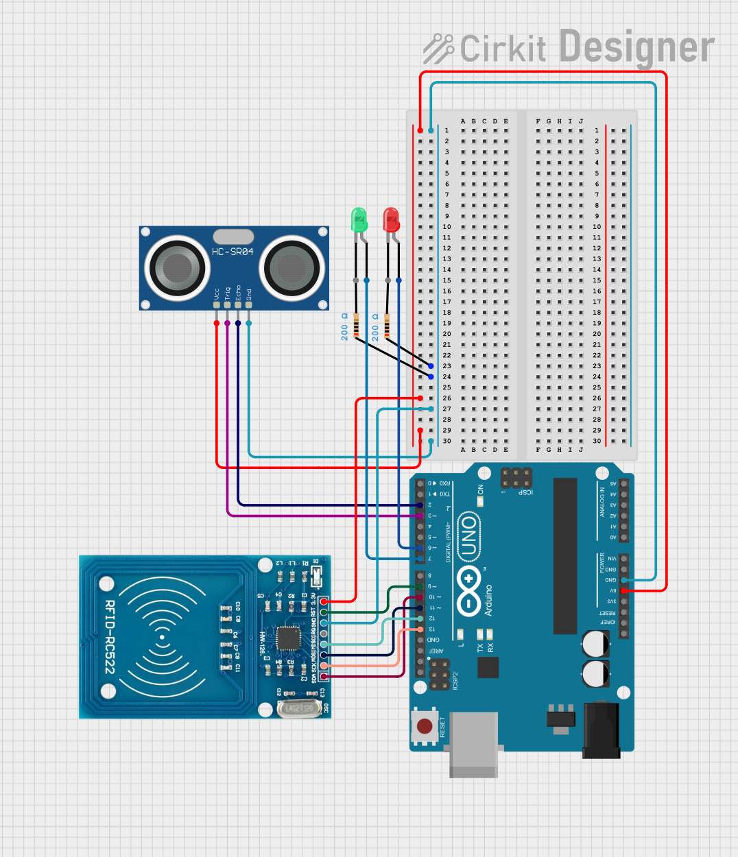
This circuit is a monitoring system for a subway platform, utilizing an Arduino UNO to control an RFID reader, an ultrasonic sensor, and two LEDs. The RFID reader authenticates users, and upon successful authentication, the ultrasonic sensor monitors for objects within 50 cm, triggering alerts if abnormal behavior is detected. The LEDs provide visual feedback for the system's status.
Arduino UNO Controlled Robotics System with RFID and Ultrasonic Sensing
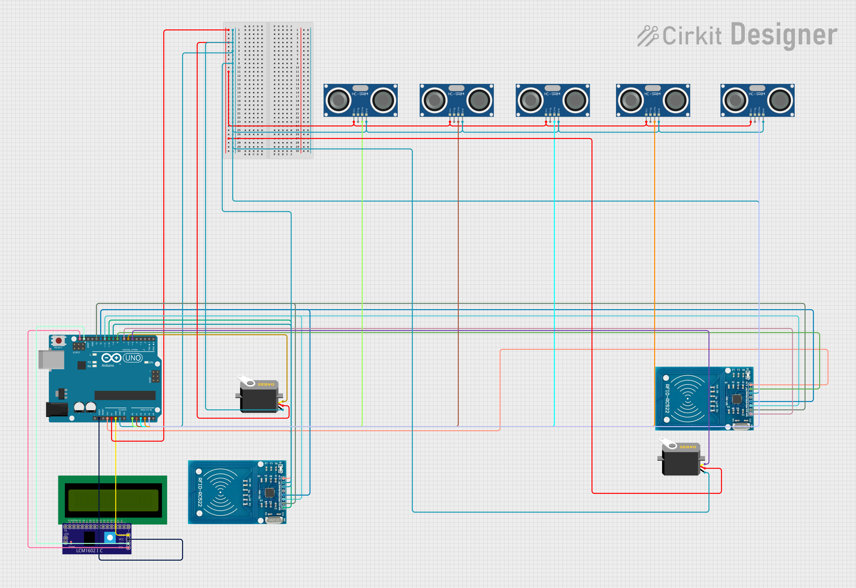
This is a multi-sensor system with actuation and display capabilities, featuring an Arduino UNO that controls ultrasonic sensors for distance measurement, servos for movement, RFID modules for identification tasks, and an LCD for output display. The system is designed for interactive applications that require environmental sensing, object manipulation, and user feedback.
Explore Projects Built with Multimétro
Arduino UNO-Based Sensor Monitoring and GSM Communication System
This is a multifunctional Arduino-based system designed to interface with an ultrasonic sensor for distance measurement, an IR sensor for object detection, a GPS module for location tracking, a GSM module for cellular communication, an I2C LCD display for user interface, and an OV7670 camera module for image capture. The Arduino manages sensor data processing and module communication, indicating a complex application such as a security or surveillance device with remote reporting capabilities.
Arduino-Powered Environmental Monitoring Station with OLED Display and Solar Charging
This is a multi-sensor environmental monitoring system with data display capabilities, powered by renewable energy. It collects data from various sensors, displays information on OLED and LCD screens, and includes motor actuators for responsive actions, all controlled by Arduino UNO microcontrollers.
Arduino UNO-Based RFID and Ultrasonic Sensor Security System with LED Indicators
This circuit is a monitoring system for a subway platform, utilizing an Arduino UNO to control an RFID reader, an ultrasonic sensor, and two LEDs. The RFID reader authenticates users, and upon successful authentication, the ultrasonic sensor monitors for objects within 50 cm, triggering alerts if abnormal behavior is detected. The LEDs provide visual feedback for the system's status.
Arduino UNO Controlled Robotics System with RFID and Ultrasonic Sensing
This is a multi-sensor system with actuation and display capabilities, featuring an Arduino UNO that controls ultrasonic sensors for distance measurement, servos for movement, RFID modules for identification tasks, and an LCD for output display. The system is designed for interactive applications that require environmental sensing, object manipulation, and user feedback.
Common Applications and Use Cases
- Circuit Testing: Verify the functionality of electronic circuits by measuring voltage, current, and resistance.
- Troubleshooting: Identify and diagnose issues in electrical systems and components.
- Component Testing: Check the health and specifications of individual electronic components.
- Battery Testing: Measure the voltage of batteries to determine their charge level.
- Continuity Testing: Ensure that electrical connections are intact and continuous.
Technical Specifications
Key Technical Details
| Specification | Value |
|---|---|
| Voltage Range | 200mV to 1000V (DC), 200mV to 750V (AC) |
| Current Range | 200µA to 10A (DC), 200µA to 10A (AC) |
| Resistance Range | 200Ω to 20MΩ |
| Display Type | Digital (LCD) |
| Accuracy | ±(0.5%+2) for DC Voltage |
| Power Supply | 9V Battery |
| Dimensions | 150mm x 70mm x 30mm |
| Weight | 200g |
Pin Configuration and Descriptions
| Pin Name | Description |
|---|---|
| COM | Common ground connection |
| VΩmA | Input for voltage, resistance, and current (up to 200mA) measurements |
| 10A | Input for high current measurements (up to 10A) |
Usage Instructions
How to Use the Multimeter in a Circuit
- Power On: Turn on the multimeter by rotating the dial to the desired measurement type (e.g., voltage, current, resistance).
- Select Range: Choose the appropriate range for the measurement. If unsure, start with the highest range and work downwards.
- Connect Probes:
- Voltage Measurement: Connect the red probe to the VΩmA port and the black probe to the COM port. Place the probes across the component or circuit where the voltage is to be measured.
- Current Measurement: For currents up to 200mA, connect the red probe to the VΩmA port. For currents up to 10A, connect the red probe to the 10A port. Place the probes in series with the circuit.
- Resistance Measurement: Connect the red probe to the VΩmA port and the black probe to the COM port. Place the probes across the component whose resistance is to be measured.
- Read Measurement: Observe the reading on the digital display.
Important Considerations and Best Practices
- Safety First: Always ensure the multimeter is set to the correct measurement type and range before connecting it to a circuit.
- Avoid Overloading: Do not exceed the maximum input ratings for voltage, current, and resistance to prevent damage to the multimeter.
- Proper Connections: Ensure that the probes are securely connected to the multimeter and the circuit/component being tested.
- Battery Check: Regularly check and replace the multimeter's battery to ensure accurate readings.
Troubleshooting and FAQs
Common Issues Users Might Face
No Display or Inaccurate Readings:
- Solution: Check the battery and replace it if necessary. Ensure the probes are properly connected and the dial is set to the correct measurement type and range.
Multimeter Not Powering On:
- Solution: Verify that the battery is installed correctly and has sufficient charge. Replace the battery if needed.
Erratic or Fluctuating Readings:
- Solution: Ensure stable connections and avoid touching the metal parts of the probes during measurement. Check for any loose or damaged components in the circuit.
Solutions and Tips for Troubleshooting
- Check Connections: Ensure all connections are secure and the probes are in good condition.
- Verify Settings: Double-check that the multimeter is set to the correct measurement type and range.
- Inspect Probes: Look for any signs of wear or damage on the probes and replace them if necessary.
- Consult Manual: Refer to the multimeter's user manual for specific troubleshooting steps and additional information.
By following these guidelines and best practices, users can effectively utilize their multimeter for a wide range of electrical measurements and troubleshooting tasks.