
How to Use 7-Segment Panel Ammeter: Examples, Pinouts, and Specs
 Design with 7-Segment Panel Ammeter in Cirkit Designer
Introduction
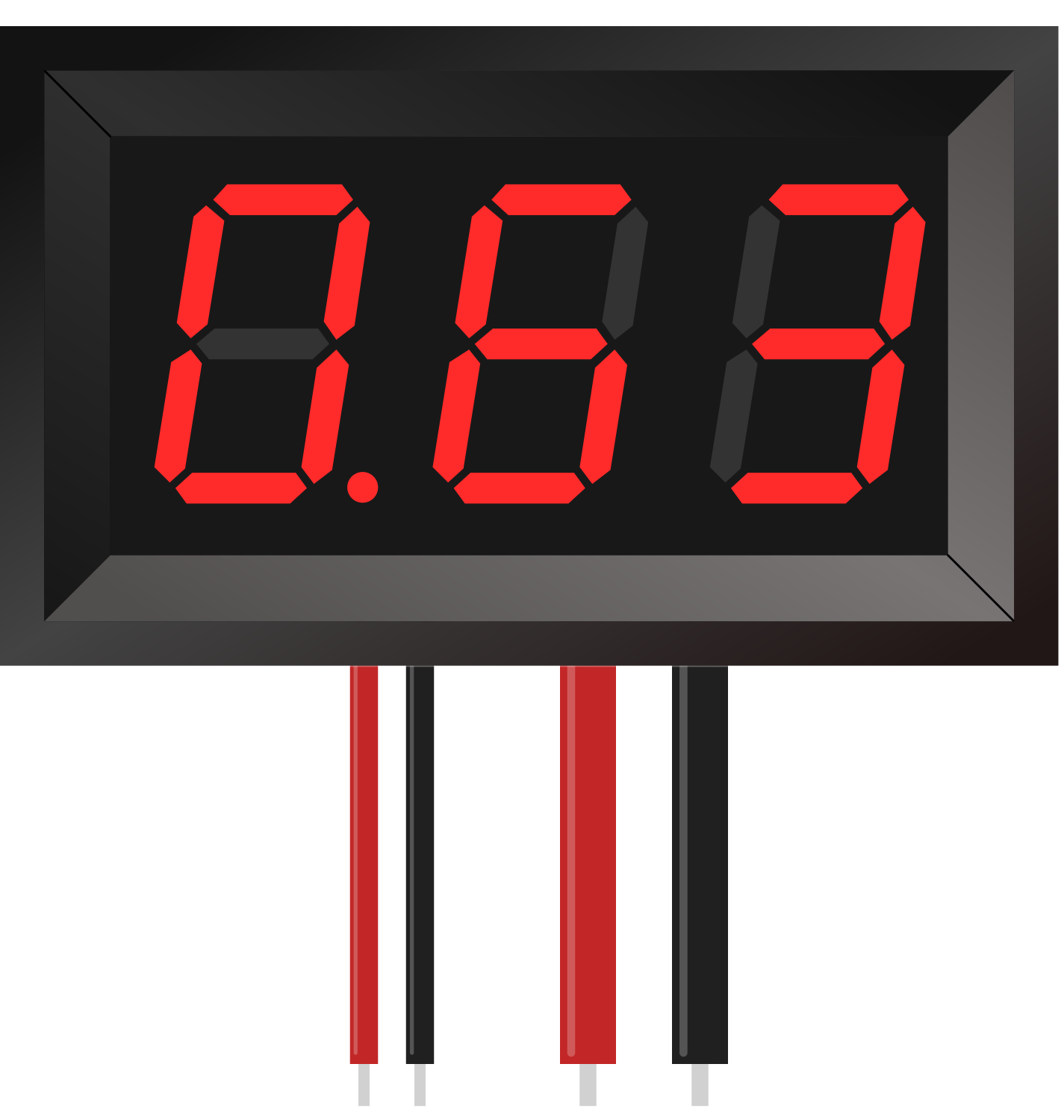
A 7-segment panel ammeter is a display device used to measure and visually represent electric current in a circuit. It utilizes seven individual segments to form digits, allowing for easy reading of current values. This component is widely used in applications where monitoring current is critical, such as in power supplies, battery chargers, and industrial equipment.
Explore Projects Built with 7-Segment Panel Ammeter
 Open Project in Cirkit Designer
 Open Project in Cirkit Designer
 Open Project in Cirkit Designer
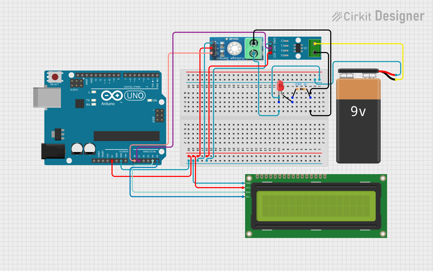 Open Project in Cirkit Designer
Explore Projects Built with 7-Segment Panel Ammeter
Open Project in Cirkit DesignerOpen Project in Cirkit DesignerOpen Project in Cirkit DesignerOpen Project in Cirkit DesignerCommon Applications and Use Cases
- Monitoring current in DC power supplies
- Measuring current in battery charging circuits
- Industrial control panels
- DIY electronics projects
- Educational tools for understanding current measurement
Technical Specifications
Below are the key technical details for a typical 7-segment panel ammeter:
| Parameter | Specification |
|---|---|
| Operating Voltage | 4.5V to 30V DC |
| Measuring Range | 0A to 10A (varies by model) |
| Display Type | 7-segment LED |
| Display Color | Red, Green, or Blue (varies by model) |
| Accuracy | ±1% |
| Input Impedance | Low (requires shunt resistor) |
| Refresh Rate | ~2-3 readings per second |
| Operating Temperature | -10°C to 50°C |
| Dimensions | Typically 48mm x 29mm x 21mm |
Pin Configuration and Descriptions
The 7-segment panel ammeter typically has three or four wires for connection. Below is the pin configuration:
| Wire Color | Function | Description |
|---|---|---|
| Red | Power Supply (Vcc) | Connect to the positive terminal of the power source. |
| Black | Ground (GND) | Connect to the negative terminal of the power source. |
| Yellow | Current Measurement Input (+) | Connect to the positive side of the load circuit. |
| Black (shared) | Current Measurement Input (-) | Connect to the negative side of the load circuit. |
Note: Some models may use different wire colors or configurations. Always refer to the datasheet of your specific model.
Usage Instructions
How to Use the Component in a Circuit
Power the Ammeter:
- Connect the red wire to the positive terminal of a DC power source (e.g., 5V or 12V).
- Connect the black wire to the negative terminal of the same power source.
Connect the Ammeter to Measure Current:
- Insert the ammeter in series with the load circuit.
- Connect the yellow wire to the positive side of the load.
- Connect the black wire (shared ground) to the negative side of the load.
Shunt Resistor (if required):
- For high-current measurements, use an external shunt resistor as specified in the ammeter's datasheet.
- Ensure the shunt resistor is rated for the expected current range.
Important Considerations and Best Practices
- Polarity: Ensure correct polarity when connecting the wires. Reversing the connections may damage the ammeter.
- Voltage Range: Do not exceed the specified operating voltage range to avoid damaging the display.
- Current Range: Ensure the measured current does not exceed the ammeter's maximum rating.
- Shunt Resistor Placement: Place the shunt resistor as close as possible to the ammeter to minimize errors caused by wire resistance.
- Isolation: Avoid connecting the ammeter directly to high-voltage circuits without proper isolation.
Example: Using with Arduino UNO
The 7-segment panel ammeter is typically a standalone device and does not require direct interfacing with an Arduino. However, you can use an Arduino to monitor current indirectly by measuring the voltage across a shunt resistor. Below is an example code snippet:
// Arduino code to measure current using a shunt resistor
// and display the value on the Serial Monitor

const int analogPin = A0;  // Analog pin connected to shunt resistor
const float shuntResistance = 0.1; // Shunt resistor value in ohms
const float voltageRef = 5.0;      // Reference voltage of Arduino (5V)

void setup() {
  Serial.begin(9600); // Initialize Serial Monitor
}

void loop() {
  int analogValue = analogRead(analogPin); // Read analog value
  float voltage = (analogValue / 1023.0) * voltageRef; // Convert to voltage
  float current = voltage / shuntResistance; // Calculate current (Ohm's Law)

  // Print current value to Serial Monitor
  Serial.print("Current: ");
  Serial.print(current, 2); // Display current with 2 decimal places
  Serial.println(" A");

  delay(1000); // Update every second
}
Note: This code assumes a shunt resistor is connected between the load and ground, with one side of the resistor connected to the Arduino's analog input.
Troubleshooting and FAQs
Common Issues and Solutions
Display Not Turning On:
- Check the power supply voltage and ensure it is within the operating range.
- Verify all connections are secure and correct.
Incorrect Current Reading:
- Ensure the ammeter is connected in series with the load.
- Verify the shunt resistor value matches the ammeter's specifications.
- Check for loose or corroded connections.
Flickering Display:
- Ensure the power supply is stable and free from noise.
- Use decoupling capacitors near the ammeter's power input if necessary.
Overload Indication:
- If the display shows an overload symbol (e.g., "OL"), reduce the current in the circuit.
- Verify the current does not exceed the ammeter's maximum rating.
FAQs
Q: Can I use the 7-segment panel ammeter with an AC circuit?
A: No, this ammeter is designed for DC circuits only. For AC current measurement, use an AC ammeter or a current transformer.
Q: Do I need a separate power supply for the ammeter?
A: Some models can be powered directly from the measured circuit, while others require a separate power supply. Check your model's datasheet for details.
Q: Can I extend the wires for the ammeter?
A: Yes, but use appropriately rated wires to minimize resistance and avoid measurement errors.
Q: What happens if I exceed the maximum current rating?
A: Exceeding the maximum current rating may damage the ammeter or cause inaccurate readings. Always use a shunt resistor for high-current applications.
By following this documentation, you can effectively use a 7-segment panel ammeter in your projects and troubleshoot common issues with ease.