
How to Use Molex Picoblade Series Header: Examples, Pinouts, and Specs
 Design with Molex Picoblade Series Header in Cirkit Designer
Introduction
The Molex Picoblade Series Header (Part ID: 0532610619) is a compact and reliable connector designed for high-density applications. With its low-profile design and versatile pin count options, it is ideal for use in electronic devices where space is limited. This header is widely used in consumer electronics, industrial equipment, and automotive systems due to its robust construction and dependable performance.
Explore Projects Built with Molex Picoblade Series Header
 Open Project in Cirkit Designer
 Open Project in Cirkit Designer
 Open Project in Cirkit Designer
 Open Project in Cirkit Designer
Explore Projects Built with Molex Picoblade Series Header
Open Project in Cirkit DesignerOpen Project in Cirkit DesignerOpen Project in Cirkit DesignerOpen Project in Cirkit DesignerCommon Applications
- Consumer electronics (e.g., wearables, handheld devices)
- Industrial control systems
- Automotive electronics
- Medical devices
- Robotics and IoT applications
Technical Specifications
Key Technical Details
| Parameter | Value |
|---|---|
| Manufacturer | Molex |
| Series | Picoblade |
| Part Number | 0532610619 |
| Number of Positions | 6 |
| Pitch | 1.25 mm |
| Mounting Type | Through Hole |
| Current Rating | 1.0 A per contact |
| Voltage Rating | 125 V AC/DC |
| Operating Temperature | -40°C to +105°C |
| Contact Material | Phosphor Bronze |
| Contact Plating | Tin |
| Housing Material | Nylon 66 (UL 94V-0 rated) |
Pin Configuration and Descriptions
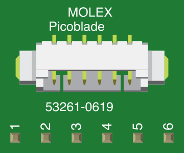
The Molex Picoblade Series Header (6-pin version) has the following pin configuration:
| Pin Number | Description | Notes |
|---|---|---|
| 1 | Signal/Power Line 1 | Connects to the first signal |
| 2 | Signal/Power Line 2 | Connects to the second signal |
| 3 | Signal/Power Line 3 | Connects to the third signal |
| 4 | Signal/Power Line 4 | Connects to the fourth signal |
| 5 | Signal/Power Line 5 | Connects to the fifth signal |
| 6 | Ground (GND) | Common ground connection |
Usage Instructions
How to Use the Component in a Circuit
Soldering the Header:
- Align the header pins with the through-hole pads on the PCB.
- Use a soldering iron with a fine tip to solder each pin securely. Ensure no solder bridges form between adjacent pins.
Mating with a Connector:
- Use a compatible Molex Picoblade receptacle (e.g., Molex 0510210600) to connect wires to the header.
- Ensure the connector is properly aligned with the header to avoid damage.
Wiring:
- Connect the wires from the receptacle to the appropriate components in your circuit.
- Verify the pinout to ensure correct connections for power, ground, and signals.
Important Considerations and Best Practices
- Current and Voltage Ratings: Do not exceed the specified current (1.0 A per contact) or voltage (125 V AC/DC) ratings to avoid overheating or damage.
- Operating Environment: Ensure the component operates within the specified temperature range (-40°C to +105°C).
- Connector Mating: Use only compatible Molex Picoblade connectors to ensure a secure and reliable connection.
- PCB Design: When designing the PCB, maintain a 1.25 mm pitch between pads to match the header's pin spacing.
Example: Connecting to an Arduino UNO
The Molex Picoblade Series Header can be used to connect sensors or other peripherals to an Arduino UNO. Below is an example of how to connect a sensor using the header:
Circuit Diagram
- Pin 1: Sensor Signal Output → Arduino Digital Pin 2
- Pin 6: Ground → Arduino GND
Arduino Code Example
// Example code to read a digital signal from a sensor connected via the
// Molex Picoblade Series Header to Arduino Digital Pin 2.

const int sensorPin = 2;  // Pin connected to the sensor signal
const int ledPin = 13;    // Built-in LED for status indication

void setup() {
  pinMode(sensorPin, INPUT);  // Set sensor pin as input
  pinMode(ledPin, OUTPUT);    // Set LED pin as output
  Serial.begin(9600);         // Initialize serial communication
}

void loop() {
  int sensorValue = digitalRead(sensorPin);  // Read the sensor value

  if (sensorValue == HIGH) {
    digitalWrite(ledPin, HIGH);  // Turn on LED if sensor is active
    Serial.println("Sensor is active!");
  } else {
    digitalWrite(ledPin, LOW);   // Turn off LED if sensor is inactive
    Serial.println("Sensor is inactive.");
  }

  delay(500);  // Wait for 500 milliseconds
}
Troubleshooting and FAQs
Common Issues
Loose Connections:
- Problem: The header or receptacle is not securely connected, causing intermittent signals.
- Solution: Ensure the connector is fully seated and aligned with the header.
Soldering Problems:
- Problem: Cold solder joints or solder bridges between pins.
- Solution: Reheat the solder joints and ensure proper solder flow. Use a solder wick to remove excess solder.
Incorrect Pinout:
- Problem: Signals or power lines are connected to the wrong pins.
- Solution: Double-check the pin configuration and wiring before powering the circuit.
Overcurrent or Overvoltage:
- Problem: Exceeding the current or voltage ratings damages the header.
- Solution: Use the component within its specified ratings. Add current-limiting resistors or voltage regulators if necessary.
FAQs
Q1: Can I use the Molex Picoblade Series Header for high-power applications?
A1: No, the header is rated for a maximum current of 1.0 A per contact and a voltage of 125 V AC/DC. It is not suitable for high-power applications.
Q2: What tools are recommended for soldering this header?
A2: Use a fine-tip soldering iron (e.g., 25-30 W) and 0.5 mm solder wire for precise soldering.
Q3: Is the header compatible with other Molex connector series?
A3: No, the Molex Picoblade Series Header is specifically designed to mate with Picoblade receptacles. Using other connector series may result in an improper fit.
Q4: Can I use this header in outdoor applications?
A4: The header is not waterproof or weatherproof. For outdoor use, additional protection (e.g., an enclosure) is required.