
How to Use Traffic light: Examples, Pinouts, and Specs
 Design with Traffic light in Cirkit Designer
Introduction
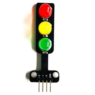
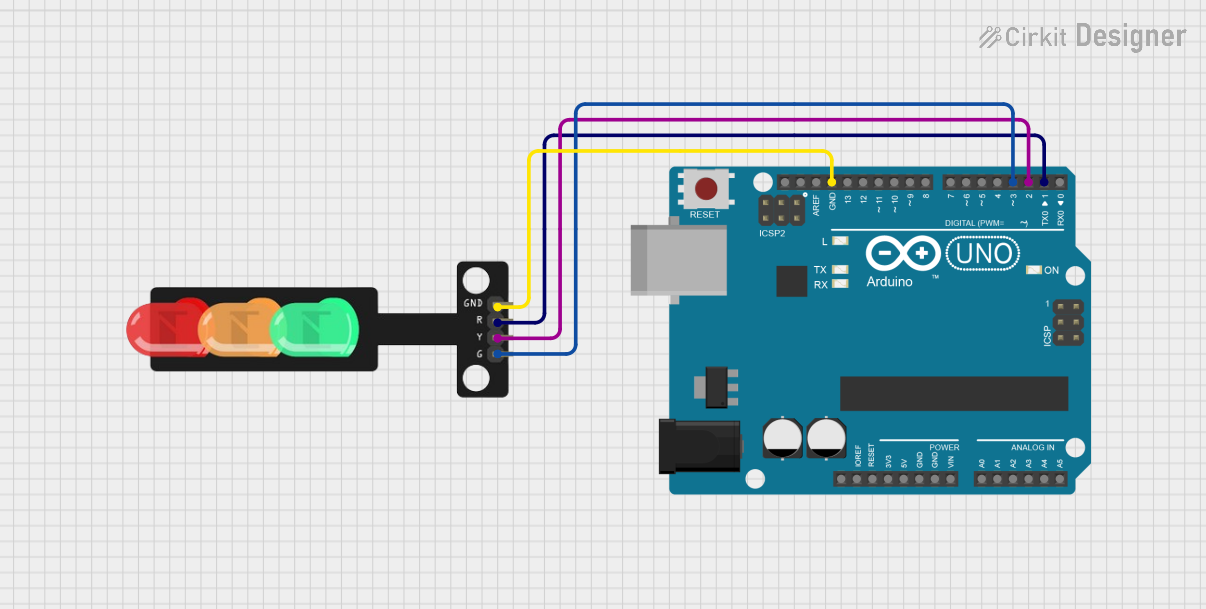
The Traffic Light is a signaling device designed to control traffic flow at intersections. It uses three colored lights—red, yellow, and green—to indicate stop, caution, and go, respectively. This component is commonly used in educational projects, prototyping, and IoT applications to simulate real-world traffic systems. The Traffic Light module is compatible with Arduino UNO (Manufacturer Part ID: UNO) and can be easily integrated into various projects.
Explore Projects Built with Traffic light
 Open Project in Cirkit Designer
 Open Project in Cirkit Designer
 Open Project in Cirkit Designer
 Open Project in Cirkit Designer
Explore Projects Built with Traffic light
Open Project in Cirkit DesignerOpen Project in Cirkit DesignerOpen Project in Cirkit DesignerOpen Project in Cirkit DesignerCommon Applications and Use Cases
- Traffic system simulations for educational purposes
- Smart city and IoT-based traffic management systems
- Robotics and autonomous vehicle projects
- Prototyping for real-world traffic control systems
Technical Specifications
The Traffic Light module typically consists of three LEDs (red, yellow, and green) and may include resistors for current limiting. Below are the key technical details:
Key Technical Details
- Operating Voltage: 5V DC (compatible with Arduino UNO)
- Current Consumption: ~20mA per LED
- LED Colors: Red, Yellow, Green
- Control Method: Digital pins on Arduino
- Dimensions: Varies based on the module (e.g., 30mm x 70mm)
Pin Configuration and Descriptions
The Traffic Light module typically has four pins for connection. The table below describes each pin:
| Pin Name | Description | Connection |
|---|---|---|
| GND | Ground pin | Connect to Arduino GND |
| VCC | Power supply pin (5V) | Connect to Arduino 5V |
| RED | Red LED control pin | Connect to a digital pin |
| YELLOW | Yellow LED control pin | Connect to a digital pin |
| GREEN | Green LED control pin | Connect to a digital pin |
Usage Instructions
How to Use the Traffic Light in a Circuit
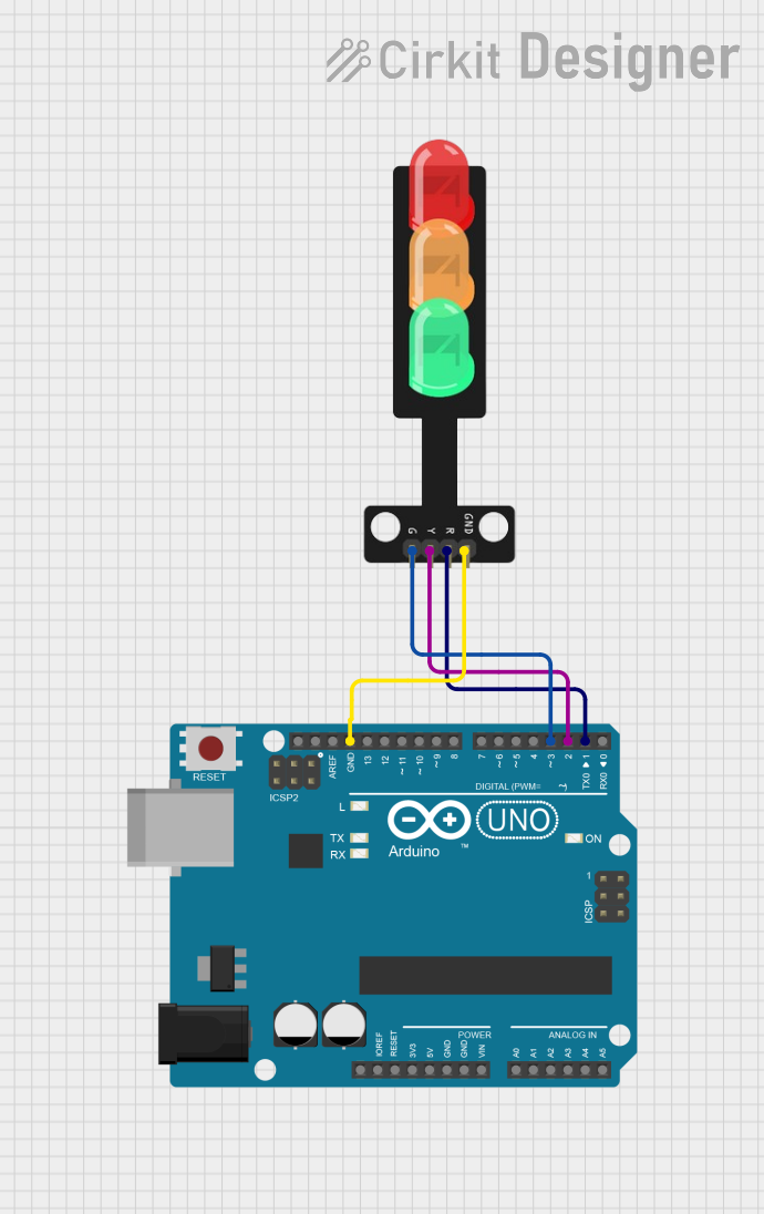
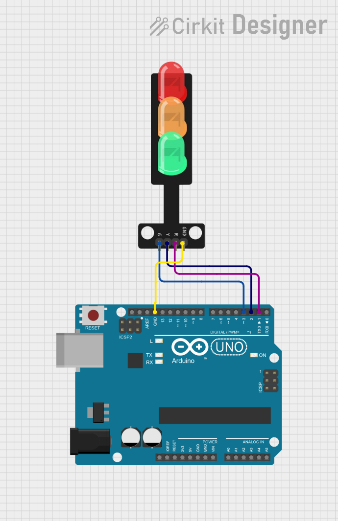
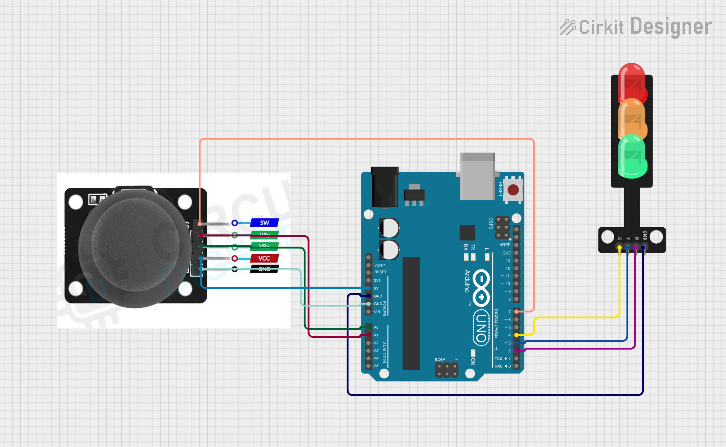
Connect the Module to Arduino UNO:
- Connect the
GNDpin of the Traffic Light module to theGNDpin on the Arduino UNO. - Connect the
VCCpin of the module to the5Vpin on the Arduino UNO. - Connect the
RED,YELLOW, andGREENpins to three digital pins on the Arduino UNO (e.g., pins 8, 9, and 10).
- Connect the
Write and Upload Code:
- Use the Arduino IDE to write a program that controls the Traffic Light module.
- Upload the code to the Arduino UNO using a USB cable.
Power the Circuit:
- Once the code is uploaded, power the Arduino UNO using a USB cable or an external power source.
Important Considerations and Best Practices
- Always use current-limiting resistors (if not already included in the module) to prevent damage to the LEDs.
- Ensure proper grounding to avoid flickering or inconsistent behavior.
- Use delays in your code to simulate realistic traffic light timing.
Example Code for Arduino UNO
Below is an example code to simulate a basic traffic light sequence:
// Define pins for the Traffic Light module
const int redPin = 8;    // Pin connected to the red LED
const int yellowPin = 9; // Pin connected to the yellow LED
const int greenPin = 10; // Pin connected to the green LED

void setup() {
  // Set the LED pins as output
  pinMode(redPin, OUTPUT);
  pinMode(yellowPin, OUTPUT);
  pinMode(greenPin, OUTPUT);
}

void loop() {
  // Turn on the red light and wait for 5 seconds
  digitalWrite(redPin, HIGH);
  delay(5000); // 5000ms = 5 seconds
  digitalWrite(redPin, LOW);

  // Turn on the green light and wait for 5 seconds
  digitalWrite(greenPin, HIGH);
  delay(5000); // 5000ms = 5 seconds
  digitalWrite(greenPin, LOW);

  // Turn on the yellow light and wait for 2 seconds
  digitalWrite(yellowPin, HIGH);
  delay(2000); // 2000ms = 2 seconds
  digitalWrite(yellowPin, LOW);
}
Troubleshooting and FAQs
Common Issues and Solutions
LEDs Not Lighting Up:
- Cause: Incorrect wiring or loose connections.
- Solution: Double-check the wiring and ensure all connections are secure.
LEDs Flickering:
- Cause: Insufficient grounding or power supply issues.
- Solution: Ensure the
GNDpin is properly connected to the Arduino's ground.
One LED Not Working:
- Cause: Faulty LED or incorrect pin assignment in the code.
- Solution: Test the LED with a multimeter and verify the pin assignments in the code.
Module Overheating:
- Cause: Excessive current due to missing resistors.
- Solution: Add appropriate current-limiting resistors if not already included.
FAQs
Q1: Can I use this module with a microcontroller other than Arduino UNO?
A1: Yes, the Traffic Light module can be used with other microcontrollers, provided they support 5V logic and have sufficient digital pins.
Q2: How can I modify the timing for the lights?
A2: Adjust the delay() values in the code to change the duration for each light.
Q3: Do I need external resistors for this module?
A3: Some modules include built-in resistors. If not, you must add resistors (e.g., 220Ω) to each LED to prevent damage.
Q4: Can I control the Traffic Light module using PWM?
A4: While PWM can be used to dim the LEDs, it is not typically necessary for standard traffic light simulations.
This documentation provides all the necessary details to get started with the Traffic Light module and Arduino UNO. Happy prototyping!