How to Use atmega328: Examples, Pinouts, and Specs
Introduction
The ATmega328 is an 8-bit microcontroller from the AVR family, designed by Microchip Technology. It is widely recognized for its use in embedded systems and is the core microcontroller in popular Arduino boards like the Arduino UNO. With 32 KB of flash memory, 2 KB of SRAM, and 1 KB of EEPROM, the ATmega328 is a versatile and efficient solution for a wide range of applications.
Explore Projects Built with atmega328


Explore Projects Built with atmega328
Common Applications and Use Cases
- Embedded Systems: Ideal for small-scale automation and control systems.
- Arduino Projects: Used in Arduino UNO and Nano boards for prototyping and development.
- IoT Devices: Suitable for low-power Internet of Things (IoT) applications.
- Robotics: Controls sensors, motors, and actuators in robotic systems.
- Home Automation: Powers smart home devices like thermostats and lighting systems.
Technical Specifications
The ATmega328 is a high-performance microcontroller with the following key specifications:
| Parameter | Value |
|---|---|
| Architecture | 8-bit AVR RISC |
| Operating Voltage | 1.8V - 5.5V |
| Flash Memory | 32 KB |
| SRAM | 2 KB |
| EEPROM | 1 KB |
| Clock Speed | Up to 20 MHz |
| I/O Pins | 23 General-Purpose I/O Pins |
| ADC Channels | 6 (10-bit resolution) |
| Timers | 2 x 8-bit, 1 x 16-bit |
| Communication Interfaces | UART, SPI, I2C |
| Power Consumption | Low-power modes available |
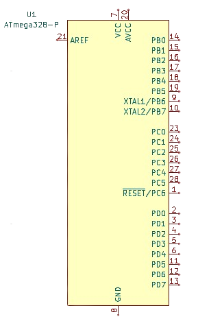
Pin Configuration and Descriptions
The ATmega328 is typically available in a 28-pin DIP (Dual Inline Package) or TQFP (Thin Quad Flat Package). Below is the pin configuration for the DIP package:
| Pin Number | Pin Name | Description |
|---|---|---|
| 1 | PC6 (RESET) | Reset input (active low) |
| 2 | PD0 (RXD) | UART Receive (Serial Communication) |
| 3 | PD1 (TXD) | UART Transmit (Serial Communication) |
| 4 | PD2 | Digital I/O or External Interrupt 0 (INT0) |
| 5 | PD3 | Digital I/O or External Interrupt 1 (INT1) |
| 6 | PD4 | Digital I/O |
| 7 | VCC | Power Supply (2.7V - 5.5V) |
| 8 | GND | Ground |
| 9 | PB6 (XTAL1) | External Oscillator Input |
| 10 | PB7 (XTAL2) | External Oscillator Output |
| 11 | PD5 | Digital I/O |
| 12 | PD6 | Digital I/O |
| 13 | PD7 | Digital I/O |
| 14 | PB0 | Digital I/O |
| 15 | PB1 | Digital I/O or PWM Output |
| 16 | PB2 | Digital I/O or PWM Output |
| 17 | PB3 | Digital I/O or PWM Output |
| 18 | PB4 | Digital I/O |
| 19 | PB5 | Digital I/O or PWM Output |
| 20 | AVCC | Analog Power Supply |
| 21 | AREF | Analog Reference Voltage |
| 22 | GND | Ground |
| 23 | PC0 (ADC0) | Analog Input Channel 0 |
| 24 | PC1 (ADC1) | Analog Input Channel 1 |
| 25 | PC2 (ADC2) | Analog Input Channel 2 |
| 26 | PC3 (ADC3) | Analog Input Channel 3 |
| 27 | PC4 (ADC4) | Analog Input Channel 4 or I2C SDA |
| 28 | PC5 (ADC5) | Analog Input Channel 5 or I2C SCL |
Usage Instructions
How to Use the ATmega328 in a Circuit
- Power Supply: Connect the VCC pin to a regulated power source (2.7V to 5.5V) and GND to ground.
- Clock Source: Use an external 16 MHz crystal oscillator connected to XTAL1 and XTAL2, along with two 22 pF capacitors to ground.
- Reset Pin: Connect a 10 kΩ pull-up resistor to the RESET pin to ensure proper operation.
- Programming: Use an ISP (In-System Programmer) or an Arduino board to upload code to the ATmega328.
- I/O Pins: Configure the digital and analog pins as needed for your application. Use pull-up or pull-down resistors for unused pins to avoid floating states.
Important Considerations and Best Practices
- Decoupling Capacitors: Place 0.1 µF capacitors close to the VCC and AVCC pins to reduce noise.
- Analog Reference: Connect the AREF pin to a stable reference voltage for accurate ADC readings.
- Unused Pins: Configure unused pins as inputs with pull-up resistors or as outputs to minimize power consumption.
- Programming Fuse Bits: Set the fuse bits correctly to configure the clock source and other settings.
Example: Using the ATmega328 with Arduino UNO
The ATmega328 is the microcontroller used in the Arduino UNO. Below is an example of controlling an LED using the ATmega328:
// This code blinks an LED connected to pin 13 of the ATmega328.
// Ensure the LED is connected with a current-limiting resistor.

void setup() {
  pinMode(13, OUTPUT); // Set pin 13 as an output
}

void loop() {
  digitalWrite(13, HIGH); // Turn the LED on
  delay(1000);            // Wait for 1 second
  digitalWrite(13, LOW);  // Turn the LED off
  delay(1000);            // Wait for 1 second
}
Troubleshooting and FAQs
Common Issues and Solutions
Microcontroller Not Responding
- Cause: Incorrect power supply or missing decoupling capacitors.
- Solution: Verify the power supply voltage and add 0.1 µF capacitors near the VCC and AVCC pins.
Program Upload Fails
- Cause: Incorrect fuse settings or faulty ISP connection.
- Solution: Check the fuse bits and ensure proper connections between the programmer and the ATmega328.
Analog Readings Are Inaccurate
- Cause: Unstable reference voltage or noise on the AREF pin.
- Solution: Use a stable voltage source for AREF and add a capacitor (e.g., 100 nF) to filter noise.
High Power Consumption
- Cause: Unused pins left floating.
- Solution: Configure unused pins as inputs with pull-up resistors or as outputs.
FAQs
Q: Can I use the ATmega328 without an external crystal?
A: Yes, the ATmega328 has an internal 8 MHz oscillator, but it is less accurate than an external crystal.Q: How do I reset the ATmega328?
A: Pull the RESET pin low momentarily to reset the microcontroller.Q: What is the maximum current per I/O pin?
A: Each I/O pin can source or sink up to 40 mA, but it is recommended to limit it to 20 mA for safe operation.Q: Can I reprogram the ATmega328 multiple times?
A: Yes, the flash memory supports up to 10,000 write/erase cycles.
This concludes the documentation for the ATmega328 microcontroller.