How to Use PC Fan: Examples, Pinouts, and Specs
Introduction
A PC fan is an essential cooling component found in computer systems. Its primary function is to maintain an optimal airflow within the computer case, facilitating the removal of excess heat generated by components such as the CPU (Central Processing Unit), GPU (Graphics Processing Unit), and power supply. By doing so, it prevents overheating, which can lead to reduced performance or hardware failure. PC fans are commonly used in desktops, servers, and even in some high-performance laptop configurations.
Explore Projects Built with PC Fan


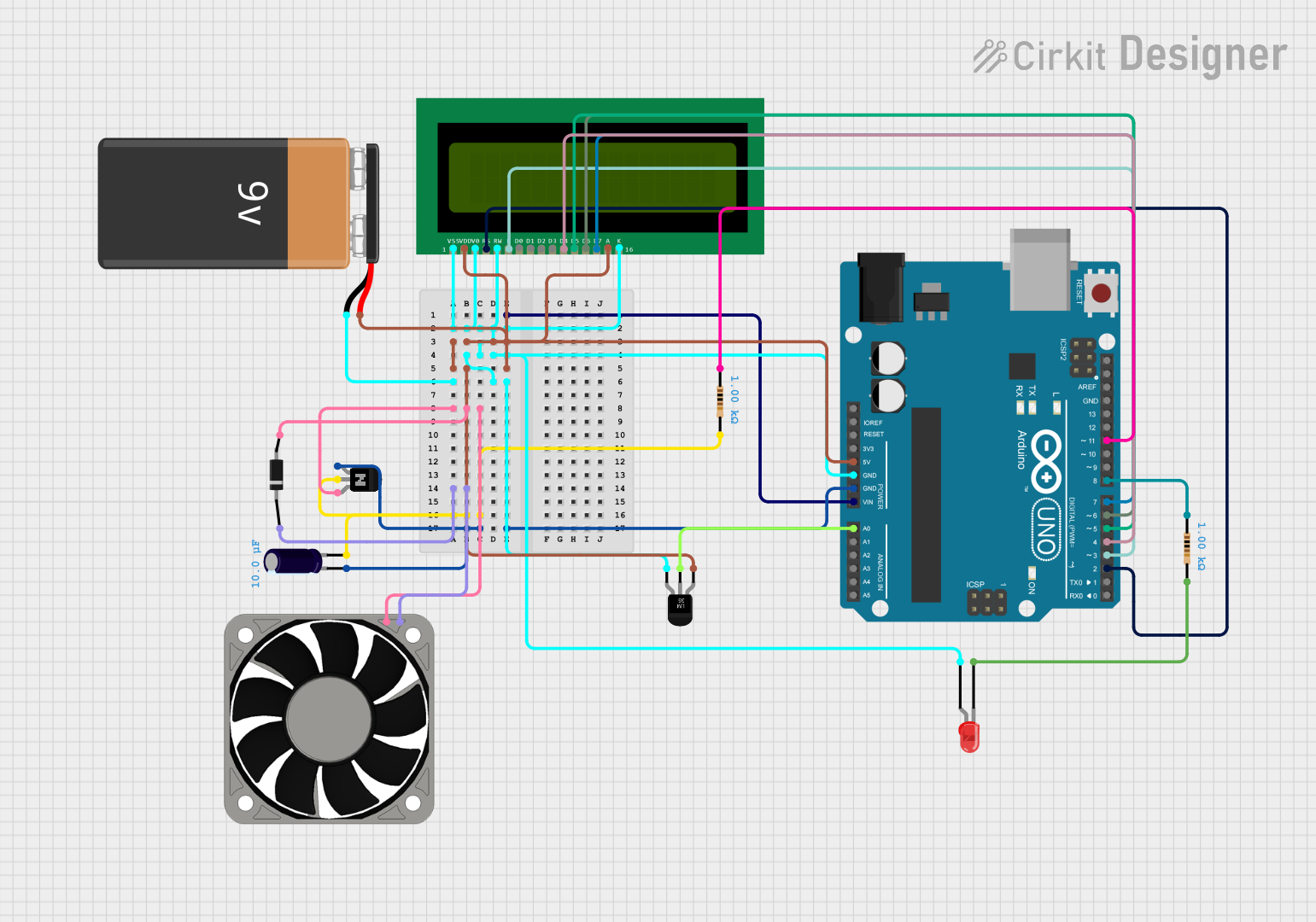
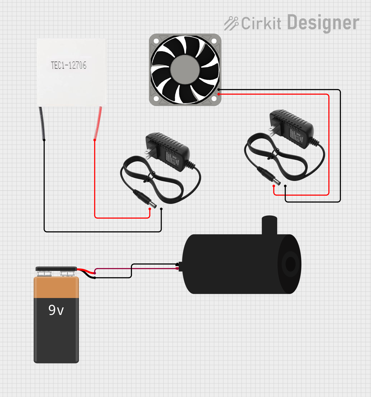
Explore Projects Built with PC Fan
Common Applications and Use Cases
- Computer Cases: To circulate air and expel hot air from the case.
- CPU Coolers: Attached to heatsinks to dissipate heat away from the CPU.
- GPU Coolers: Used on graphics cards to maintain optimal operating temperatures.
- Power Supply Units: Integrated within to prevent overheating of power components.
- Rack Cabinets: In data centers to cool server hardware.
Technical Specifications
Key Technical Details
- Voltage: Typically 12V DC for standard PC fans.
- Current: Ranges from 0.15A to 0.30A for most common fans.
- Power Ratings: Usually between 1.8W to 3.6W.
- Speed: Measured in RPM (Revolutions Per Minute), commonly between 600 RPM to 2000 RPM.
- Airflow: Measured in CFM (Cubic Feet per Minute), varies based on fan size and RPM.
- Noise Level: Measured in dBA, with quieter fans around 10-20 dBA and louder ones up to 30-40 dBA.
- Size: Common sizes include 80mm, 120mm, and 140mm.
Pin Configuration and Descriptions
| Pin Number | Description | Notes |
|---|---|---|
| 1 | Ground | Connect to system ground |
| 2 | +12V DC Supply | Power supply for the fan |
| 3 | Tachometer Signal | Outputs fan speed (RPM) signal |
| 4 | PWM Control Signal | Optional, for speed control |
Usage Instructions
How to Use the Component in a Circuit
- Power Connection: Connect the +12V DC supply to pin 2 and the ground to pin 1.
- Speed Monitoring: To monitor fan speed, connect pin 3 to a tachometer or a microcontroller capable of reading frequency.
- Speed Control (PWM Fans): For fans with PWM control, apply a PWM signal to pin 4 to regulate fan speed.
Important Considerations and Best Practices
- Ensure the fan is oriented correctly for desired airflow direction (intake or exhaust).
- Avoid obstructing the fan or airflow paths to maintain efficient cooling.
- Use appropriate screws or mounting mechanisms to secure the fan and minimize vibrations.
- Consider using a fan with a PWM control for dynamic speed adjustments based on temperature.
Troubleshooting and FAQs
Common Issues
- Fan Not Spinning: Check power connections and ensure the supply voltage is within specifications.
- Noisy Operation: Ensure the fan is securely mounted and not obstructed. Replace if bearings are worn out.
- Inaccurate Speed Readings: Verify connections to the tachometer signal and ensure there is no signal interference.
Solutions and Tips for Troubleshooting
- Intermittent Operation: Inspect for loose connections or damaged wires.
- Reduced Airflow: Clean the fan blades and surrounding area to remove dust buildup.
- Overheating Despite Fan Operation: Check for proper fan orientation and consider increasing fan speed or adding additional fans.
FAQs
Q: Can I control a 3-pin fan with a PWM signal? A: No, PWM control requires a 4-pin fan. However, you can control the speed of a 3-pin fan by varying the supply voltage.
Q: How do I know if my fan is set for intake or exhaust? A: Generally, the side of the fan where the blades are more exposed is the intake side, and the side with the frame or sticker is the exhaust side.
Q: What is the lifespan of a PC fan? A: It varies by model and usage, but most quality PC fans have a lifespan of 30,000 to 60,000 hours.
Example Arduino Code for a 4-Pin PWM Fan
// Define the PWM pin connected to the fan
const int pwmPin = 9; // For Arduino UNO, use a PWM-enabled pin

void setup() {
  // Set the PWM pin as an output
  pinMode(pwmPin, OUTPUT);
}

void loop() {
  // Set the fan speed to 50% duty cycle
  analogWrite(pwmPin, 128); // 128 out of 255 for 50%
  delay(5000); // Run at this speed for 5 seconds

  // Increase the fan speed to 75% duty cycle
  analogWrite(pwmPin, 192); // 192 out of 255 for 75%
  delay(5000); // Run at this speed for 5 seconds

  // Note: To stop the fan, use analogWrite(pwmPin, 0);
}
Note: The above code is a simple demonstration of controlling a 4-pin PWM PC fan using an Arduino UNO. The PWM signal frequency on most Arduino boards is around 490Hz, which is suitable for many PC fans. However, always check the fan's datasheet for the recommended PWM frequency and adjust the code accordingly.