How to Use keypad 1x4: Examples, Pinouts, and Specs
Introduction
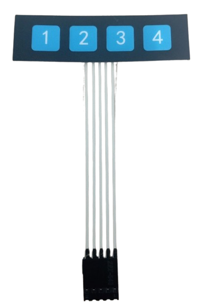
The Keypad 1x4 is a compact input device consisting of four buttons arranged in a single row. It is commonly used in electronic devices to provide user input functionality, such as menu navigation, numeric entry, or control commands. Its simple design and ease of integration make it a popular choice for projects requiring a small number of input options.
Explore Projects Built with keypad 1x4


Explore Projects Built with keypad 1x4
Common Applications and Use Cases
- Home automation systems
- Security systems (e.g., PIN entry)
- Menu navigation in embedded systems
- Control panels for appliances or devices
- Educational and DIY electronics projects
Technical Specifications
The Keypad 1x4 is a passive component that requires external circuitry to detect button presses. Below are its key technical details:
| Parameter | Value |
|---|---|
| Number of Buttons | 4 |
| Operating Voltage | 3.3V to 5V |
| Maximum Current (per button) | 10mA (typical) |
| Button Type | Momentary, normally open |
| Dimensions | Varies (typically compact) |
| Connector Type | 4-pin or 5-pin header |
Pin Configuration and Descriptions
The Keypad 1x4 typically has 4 or 5 pins, depending on the design. Below is the pinout description:
4-Pin Configuration
| Pin | Label | Description |
|---|---|---|
| 1 | Button 1 | Connects to the first button |
| 2 | Button 2 | Connects to the second button |
| 3 | Button 3 | Connects to the third button |
| 4 | Button 4 | Connects to the fourth button |
5-Pin Configuration (with Common Ground)
| Pin | Label | Description |
|---|---|---|
| 1 | Button 1 | Connects to the first button |
| 2 | Button 2 | Connects to the second button |
| 3 | Button 3 | Connects to the third button |
| 4 | Button 4 | Connects to the fourth button |
| 5 | GND | Common ground for all buttons |
Usage Instructions
How to Use the Keypad 1x4 in a Circuit
- Connect the Pins:
- For a 4-pin keypad, connect each pin to a digital input pin on your microcontroller.
- For a 5-pin keypad, connect the GND pin to the ground of your circuit, and the other pins to digital input pins.
- Pull-Down Resistors: Use pull-down resistors (typically 10kΩ) on each button pin to ensure a stable LOW state when the button is not pressed.
- Debouncing: Implement software or hardware debouncing to avoid false triggers caused by mechanical button bounce.
Example Circuit with Arduino UNO
Below is an example of how to connect a Keypad 1x4 to an Arduino UNO:
- Connect the keypad pins to Arduino digital pins 2, 3, 4, and 5.
- Use 10kΩ pull-down resistors on each button pin.
Example Arduino Code
// Keypad 1x4 Example Code for Arduino UNO
// This code reads button presses and prints the button number to the Serial Monitor.

const int buttonPins[4] = {2, 3, 4, 5}; // Define button pins
int buttonState[4];                     // Array to store button states

void setup() {
  Serial.begin(9600); // Initialize serial communication
  for (int i = 0; i < 4; i++) {
    pinMode(buttonPins[i], INPUT); // Set button pins as input
  }
}

void loop() {
  for (int i = 0; i < 4; i++) {
    buttonState[i] = digitalRead(buttonPins[i]); // Read button state
    if (buttonState[i] == HIGH) { // Check if button is pressed
      Serial.print("Button ");
      Serial.print(i + 1); // Print button number (1-based index)
      Serial.println(" is pressed");
      delay(200); // Debounce delay
    }
  }
}
Important Considerations and Best Practices
- Debouncing: Always implement debouncing to avoid erratic behavior.
- Voltage Levels: Ensure the keypad operates within the voltage range of your microcontroller.
- Mechanical Wear: Avoid excessive force on the buttons to prolong their lifespan.
- Pin Mapping: Double-check the pin mapping to avoid incorrect connections.
Troubleshooting and FAQs
Common Issues and Solutions
Buttons Not Responding
- Cause: Loose or incorrect connections.
- Solution: Verify all connections and ensure the keypad pins are securely connected to the microcontroller.
Multiple Buttons Triggering Simultaneously
- Cause: Lack of pull-down resistors or improper grounding.
- Solution: Add pull-down resistors to each button pin and ensure the GND pin (if present) is connected to the circuit ground.
Erratic Behavior
- Cause: Button bounce or noise in the circuit.
- Solution: Implement software or hardware debouncing and ensure a clean power supply.
Incorrect Button Mapping
- Cause: Misidentified pins or incorrect wiring.
- Solution: Double-check the pinout and verify the wiring matches the microcontroller code.
FAQs
Q: Can I use the Keypad 1x4 with a 3.3V microcontroller?
A: Yes, the keypad is compatible with both 3.3V and 5V systems. Ensure the pull-down resistors are appropriately sized for the voltage level.
Q: How do I extend the keypad's cable length?
A: Use shielded cables to minimize noise and interference. Keep the cable length as short as possible to maintain signal integrity.
Q: Can I use the Keypad 1x4 for analog input?
A: No, the Keypad 1x4 is designed for digital input. Use digital pins on your microcontroller to read button states.
Q: How do I add more buttons to my project?
A: You can use multiple Keypad 1x4 modules or switch to a larger keypad (e.g., 4x4) for additional input options.