How to Use Stepper Driver: Examples, Pinouts, and Specs
Introduction
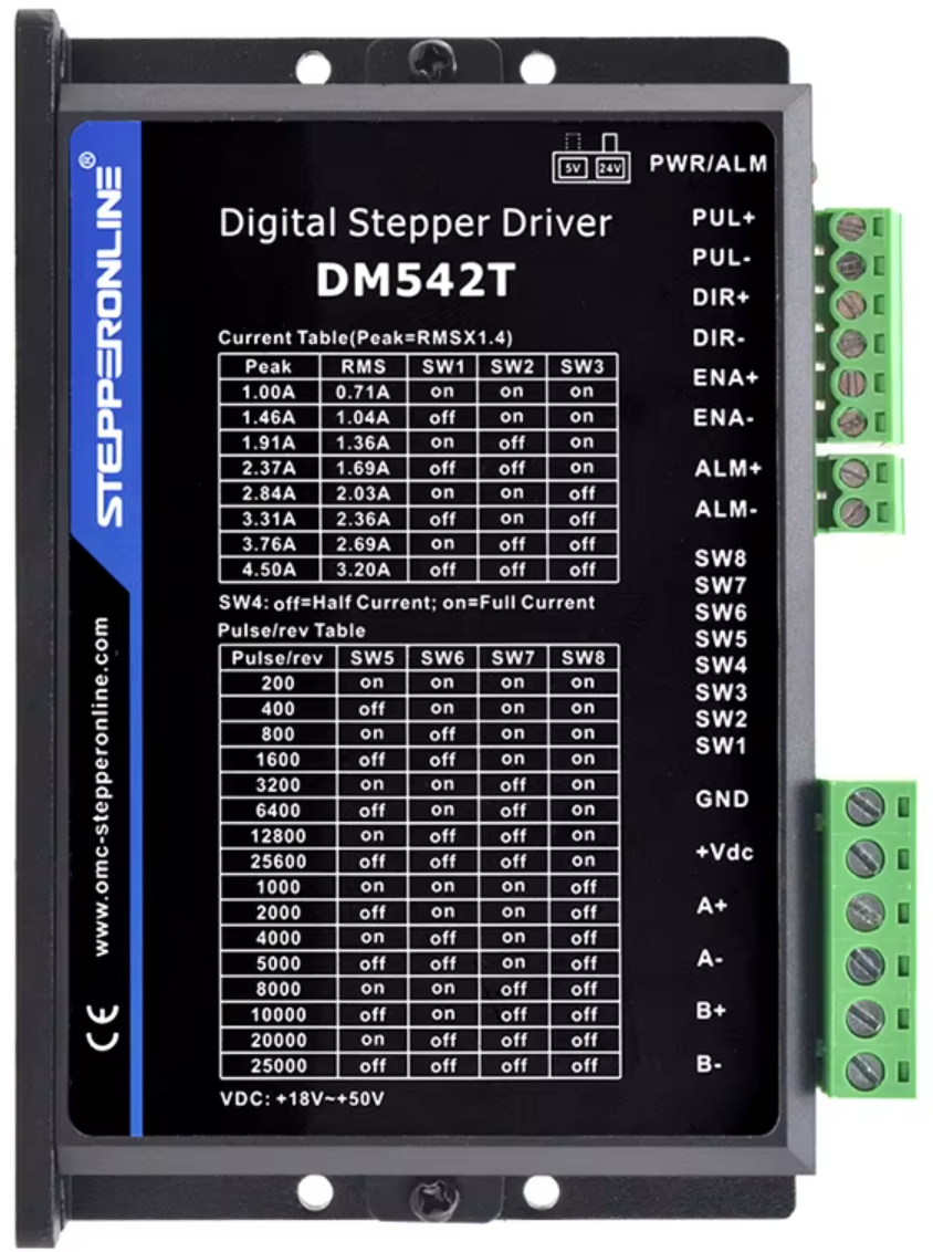
The DM542T Stepper Driver, manufactured by sTEPPERONLINE, is a high-performance microstepping driver designed to control stepper motors with precision and efficiency. It is capable of driving 2-phase and 4-phase stepper motors, making it suitable for a wide range of applications. The DM542T is particularly well-suited for CNC machines, 3D printers, robotics, and other motion control systems requiring accurate positioning and smooth operation.
Explore Projects Built with Stepper Driver


Explore Projects Built with Stepper Driver
Common Applications
- CNC machines for precise cutting and milling
- 3D printers for accurate layer deposition
- Robotics for controlled movement and positioning
- Conveyor systems in industrial automation
- Camera sliders and pan-tilt systems for smooth motion control
Technical Specifications
The DM542T Stepper Driver offers robust performance and flexibility. Below are its key technical specifications:
| Parameter | Value |
|---|---|
| Supply Voltage | 20V to 50V DC |
| Output Current Range | 1.0A to 4.2A (adjustable) |
| Microstepping Resolution | Up to 1/128 steps |
| Input Signal Voltage | 5V to 24V (compatible with TTL and CMOS) |
| Control Signal Frequency | 0 to 200 kHz |
| Operating Temperature | -10°C to +45°C |
| Dimensions | 118mm x 75.5mm x 34mm |
| Weight | 280g |
Pin Configuration and Descriptions
The DM542T features a set of input and output terminals for motor control and power connections. Below is the pin configuration:
Power and Motor Connections
| Pin Name | Description |
|---|---|
| V+ | Positive terminal for power supply (20V-50V DC) |
| V- | Negative terminal for power supply (GND) |
| A+ | Positive terminal for motor coil A |
| A- | Negative terminal for motor coil A |
| B+ | Positive terminal for motor coil B |
| B- | Negative terminal for motor coil B |
Control Signal Connections
| Pin Name | Description |
|---|---|
| PUL+ | Positive terminal for pulse signal input |
| PUL- | Negative terminal for pulse signal input |
| DIR+ | Positive terminal for direction signal input |
| DIR- | Negative terminal for direction signal input |
| ENA+ | Positive terminal for enable signal input (optional) |
| ENA- | Negative terminal for enable signal input (optional) |
Usage Instructions
How to Use the DM542T in a Circuit
- Power Supply: Connect a DC power supply (20V-50V) to the V+ and V- terminals. Ensure the power supply can provide sufficient current for the motor.
- Motor Connection: Connect the stepper motor coils to the A+, A-, B+, and B- terminals. Verify the wiring matches the motor's datasheet.
- Control Signals: Connect the PUL+, PUL-, DIR+, DIR-, and optionally ENA+ and ENA- terminals to a microcontroller or motion controller. Use appropriate resistors if needed to match signal voltage levels.
- Microstepping and Current Settings: Use the DIP switches on the driver to configure the microstepping resolution and output current. Refer to the DM542T datasheet for DIP switch settings.
- Testing: Power on the system and send pulse and direction signals from the controller to test motor movement.
Important Considerations
- Heat Dissipation: Ensure proper ventilation or use a heatsink to prevent overheating during operation.
- Signal Integrity: Use shielded cables for control signals to minimize noise interference.
- Current Settings: Set the output current to match the motor's rated current to avoid damage to the motor or driver.
- Microstepping: Choose an appropriate microstepping resolution based on the application's precision and speed requirements.
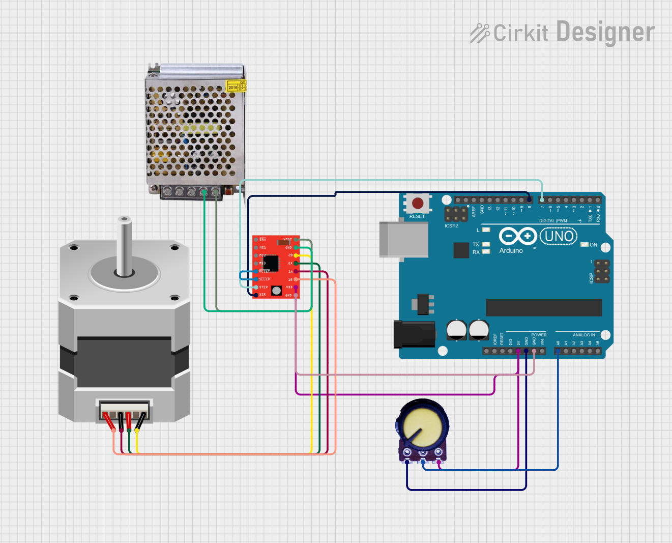
Example: Connecting to an Arduino UNO
Below is an example of how to connect the DM542T to an Arduino UNO and control a stepper motor:
Wiring Diagram
- DM542T PUL+ → Arduino Pin 9
- DM542T PUL- → Arduino GND
- DM542T DIR+ → Arduino Pin 8
- DM542T DIR- → Arduino GND
- DM542T V+ → 24V DC Power Supply Positive
- DM542T V- → 24V DC Power Supply Negative
- Motor Coils → Connect to A+, A-, B+, B- as per motor datasheet
Arduino Code
// Define pins for pulse and direction signals
const int pulsePin = 9; // Pulse signal pin
const int dirPin = 8;   // Direction signal pin

void setup() {
  // Set pulse and direction pins as outputs
  pinMode(pulsePin, OUTPUT);
  pinMode(dirPin, OUTPUT);

  // Set initial direction
  digitalWrite(dirPin, HIGH); // HIGH for one direction, LOW for the other
}

void loop() {
  // Generate pulses to move the stepper motor
  digitalWrite(pulsePin, HIGH); // Set pulse pin HIGH
  delayMicroseconds(500);       // Wait for 500 microseconds
  digitalWrite(pulsePin, LOW);  // Set pulse pin LOW
  delayMicroseconds(500);       // Wait for 500 microseconds
}
Troubleshooting and FAQs
Common Issues and Solutions
Motor Not Moving:
- Verify power supply connections and ensure the voltage is within the specified range.
- Check the control signal connections and ensure the microcontroller is sending pulses.
- Confirm the DIP switch settings for current and microstepping.
Motor Vibrates but Does Not Rotate:
- Check the wiring of the motor coils. Incorrect wiring can cause improper operation.
- Ensure the pulse signal frequency is within the driver's supported range.
Overheating:
- Ensure the driver is mounted on a heat-dissipating surface or use a heatsink.
- Verify that the output current is set correctly for the motor.
Erratic Motor Movement:
- Use shielded cables for control signals to reduce noise interference.
- Check for loose connections in the circuit.
FAQs
Q: Can the DM542T drive a unipolar stepper motor?
A: No, the DM542T is designed for bipolar stepper motors (2-phase or 4-phase).
Q: What is the maximum step rate supported by the DM542T?
A: The DM542T supports a maximum control signal frequency of 200 kHz.
Q: Is the enable signal mandatory?
A: No, the enable signal is optional. If not used, the ENA+ and ENA- terminals can be left unconnected.
Q: Can I use a 12V power supply with the DM542T?
A: No, the DM542T requires a power supply voltage between 20V and 50V DC.
By following this documentation, users can effectively integrate the DM542T Stepper Driver into their projects for precise and reliable motor control.