How to Use MSGEQ7: Examples, Pinouts, and Specs
Introduction
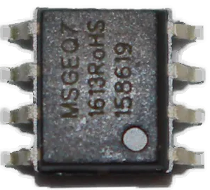
The MSGEQ7 by Mixed Signal Integration is a versatile seven band graphic equalizer display filter. It is widely used in audio analysis applications to divide the audio spectrum into seven distinct frequency bands. The frequencies are centered around 63Hz, 160Hz, 400Hz, 1kHz, 2.5kHz, 6.25kHz, and 16kHz. Each band's amplitude is output as a DC voltage, which can be used for creating visual representations of the audio spectrum, such as in spectrum analyzers and LED visualizers.
Common applications include:
- Audio equipment and visualizers
- Equalization and sound analysis
- DIY audio projects
- Interactive art installations
Explore Projects Built with MSGEQ7
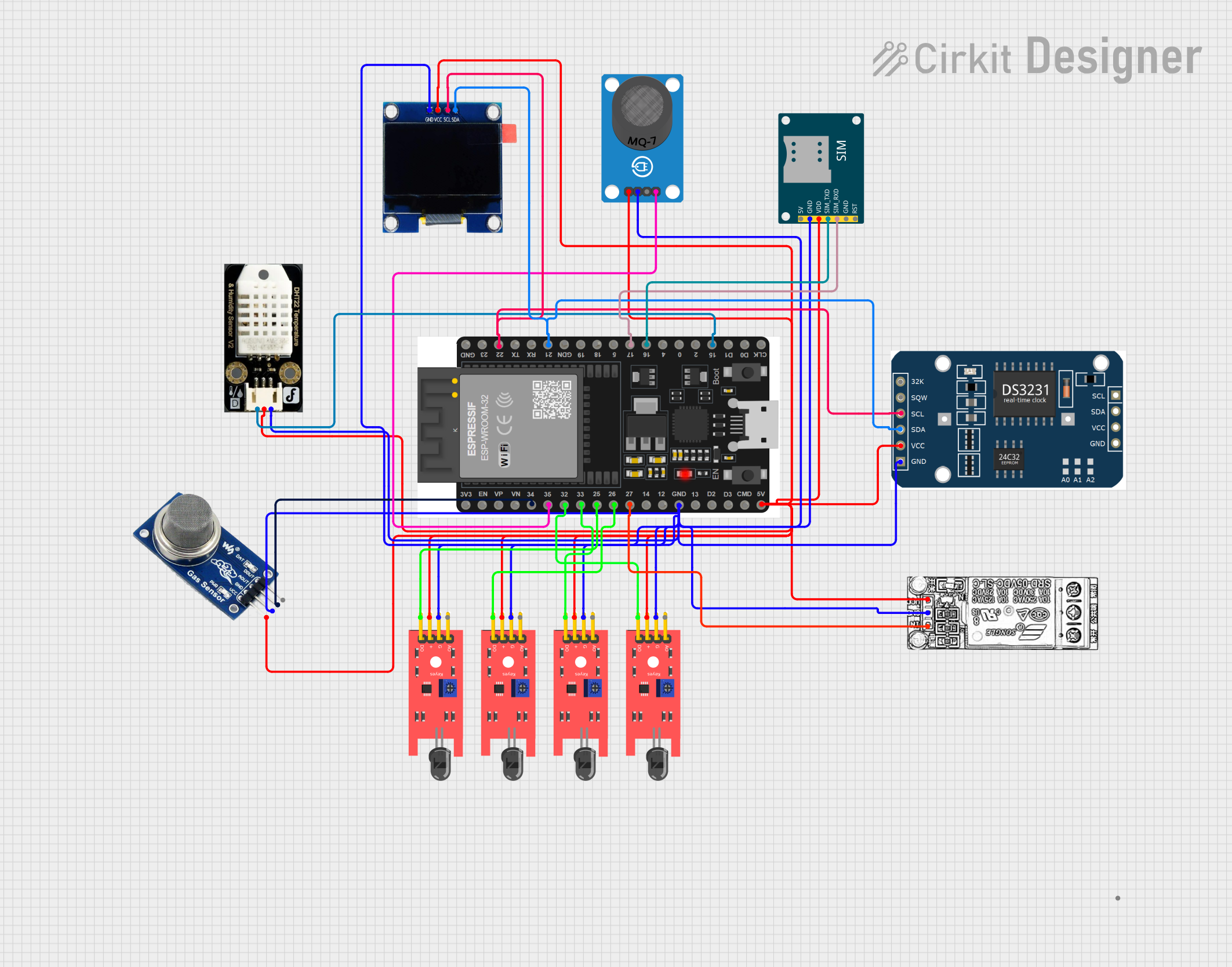
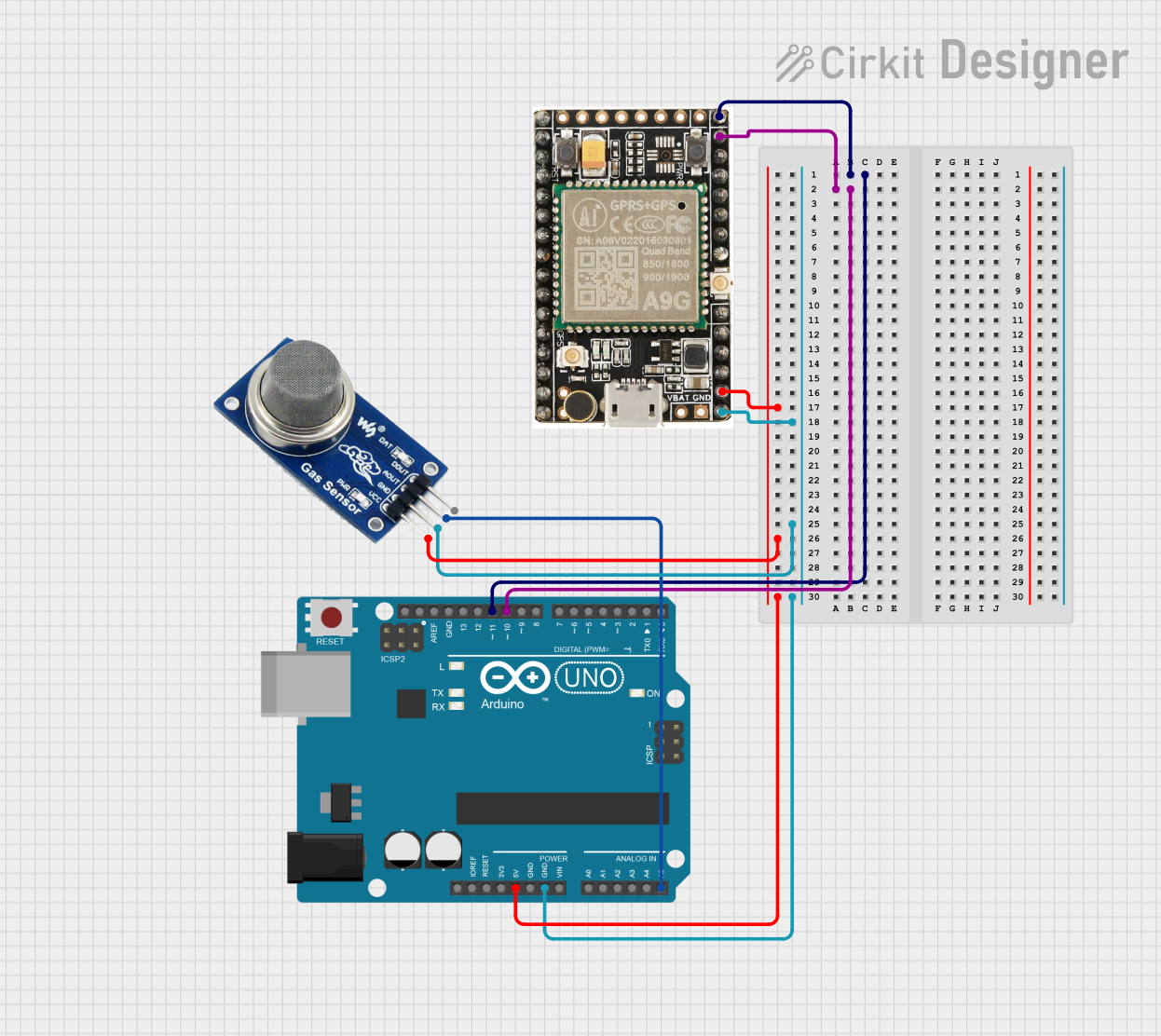
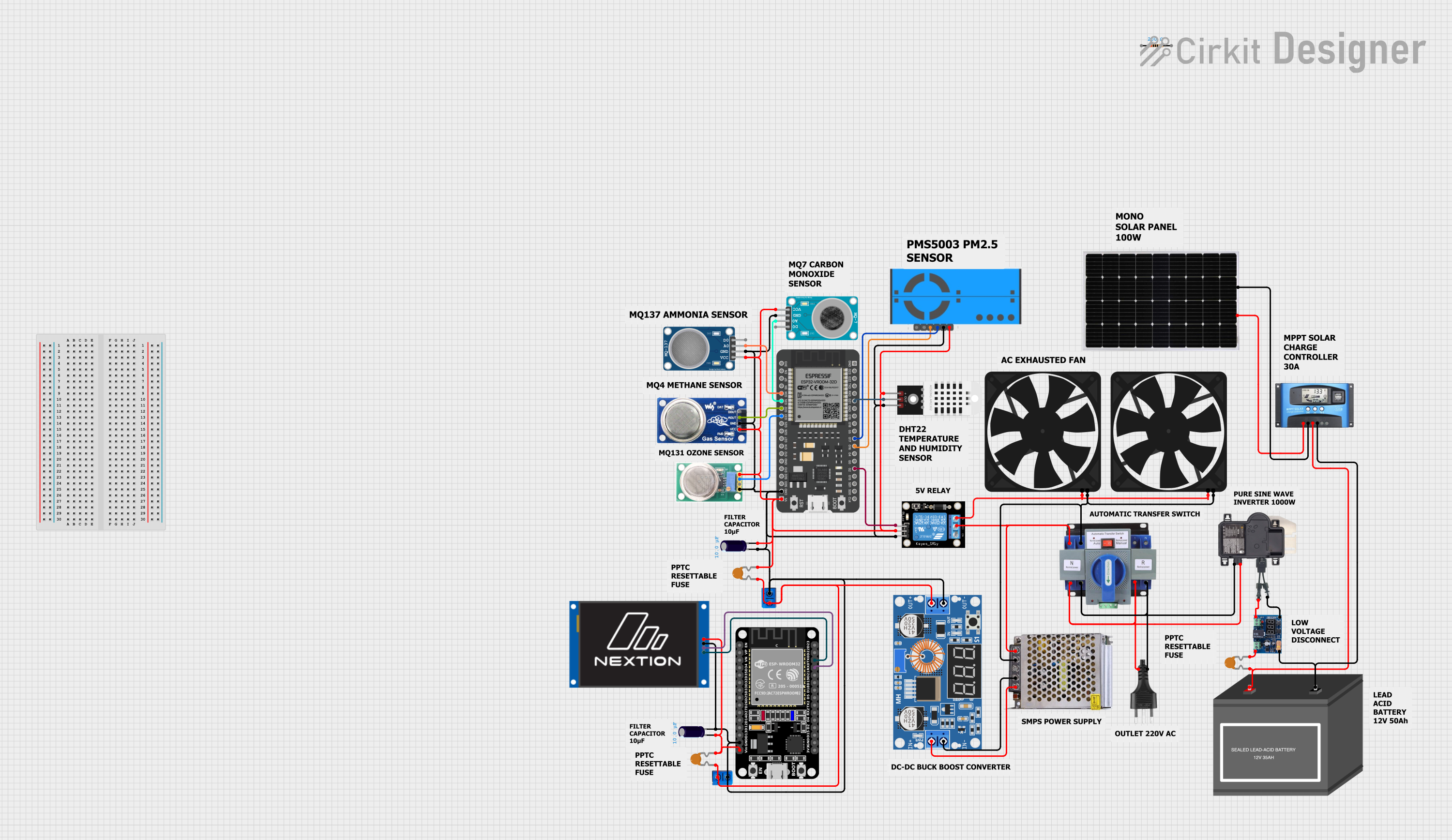
Explore Projects Built with MSGEQ7
Technical Specifications
Key Technical Details
- Power Supply: 2.7V to 5.5V
- Frequency Bands: 7 (63Hz, 160Hz, 400Hz, 1kHz, 2.5kHz, 6.25kHz, 16kHz)
- Output: Multiplexed, DC voltage representing each band's amplitude
- Package: 8-pin DIP or SOIC
Pin Configuration and Descriptions
| Pin Number | Name | Description |
|---|---|---|
| 1 | GND | Ground connection |
| 2 | VDD | Positive power supply (2.7V to 5.5V) |
| 3 | OUT | Output of the bandpass filter |
| 4 | STROBE | Strobe pin, toggled to switch between bands |
| 5 | RESET | Resets the multiplexer to the first band |
| 6 | IN | Audio input signal |
| 7 | VSS | Ground connection (same as Pin 1) |
| 8 | REF | Reference voltage for the internal ADC |
Usage Instructions
How to Use the MSGEQ7 in a Circuit
- Connect VDD (Pin 2) to your power supply (2.7V to 5.5V).
- Connect GND (Pin 1) and VSS (Pin 7) to the ground of your power supply.
- Apply the audio signal to the IN pin (Pin 6).
- Connect the OUT pin (Pin 3) to an analog input of your microcontroller to read the voltage levels.
- Use the STROBE (Pin 4) and RESET (Pin 5) pins to cycle through the frequency bands.
Important Considerations and Best Practices
- Ensure that the power supply voltage is within the specified range.
- Place a 0.1 µF bypass capacitor close to the VDD pin to filter out noise.
- Use a proper low-pass filter on the audio input to prevent aliasing.
- Keep the audio signal within the acceptable input range to avoid distortion.
Example Code for Arduino UNO
// Define the pin connections
const int analogPin = A0; // Connect OUT pin of MSGEQ7 to A0
const int strobePin = 2;  // Connect STROBE pin to digital pin 2
const int resetPin = 3;   // Connect RESET pin to digital pin 3

// Variables to store the band values
int spectrumValues[7];

void setup() {
  pinMode(analogPin, INPUT);
  pinMode(strobePin, OUTPUT);
  pinMode(resetPin, OUTPUT);
  digitalWrite(resetPin, LOW);
  digitalWrite(strobePin, HIGH);

  Serial.begin(9600); // Start serial communication at 9600 baud
}

void loop() {
  digitalWrite(resetPin, HIGH); // Reset the MSGEQ7's counter
  delayMicroseconds(5);
  digitalWrite(resetPin, LOW);

  for (int i = 0; i < 7; i++) {
    digitalWrite(strobePin, LOW); // Move to the next band
    delayMicroseconds(50); // Allow the MSGEQ7's output to settle
    spectrumValues[i] = analogRead(analogPin); // Read the band value
    digitalWrite(strobePin, HIGH);
  }

  // Print the spectrum values to the serial monitor
  for (int i = 0; i < 7; i++) {
    Serial.print("Band ");
    Serial.print(i);
    Serial.print(": ");
    Serial.println(spectrumValues[i]);
  }
  Serial.println();

  delay(50); // Delay for a short period before reading the next set of values
}
Troubleshooting and FAQs
Common Issues
- No Output on Any Band: Check power supply connections and ensure the audio input is connected and within the acceptable range.
- Inaccurate Band Readings: Ensure that there is a proper low-pass filter on the audio input and that the strobe and reset timings are correct.
- Noisy Output: Place a 0.1 µF capacitor close to the VDD pin and ensure that the audio input is clean.
Solutions and Tips for Troubleshooting
- Double-check all connections according to the pin configuration.
- Use an oscilloscope to verify the strobe and reset signals.
- Ensure that the microcontroller's analog input is functioning correctly.
FAQs
Q: Can I use the MSGEQ7 with a 3.3V system? A: Yes, the MSGEQ7 can operate from 2.7V to 5.5V, making it compatible with 3.3V systems.
Q: How can I increase the number of bands? A: To increase the number of bands, you can use multiple MSGEQ7 ICs and combine their outputs.
Q: What is the purpose of the REF pin? A: The REF pin sets the reference voltage for the internal ADC. It is typically connected to the midpoint of the power supply voltage.
This documentation provides a comprehensive guide to using the MSGEQ7 seven band graphic equalizer IC. For further information, consult the manufacturer's datasheet and application notes.