
How to Use 640x480 CMOS Color Camera: Examples, Pinouts, and Specs
 Design with 640x480 CMOS Color Camera in Cirkit Designer
Introduction
The 640x480 CMOS Color Camera is a compact imaging device designed to capture video and still images at a resolution of 640x480 pixels. It utilizes a complementary metal-oxide-semiconductor (CMOS) sensor, which is known for its low power consumption and high-speed performance. This camera is ideal for applications requiring efficient image capture in a small form factor.
Explore Projects Built with 640x480 CMOS Color Camera
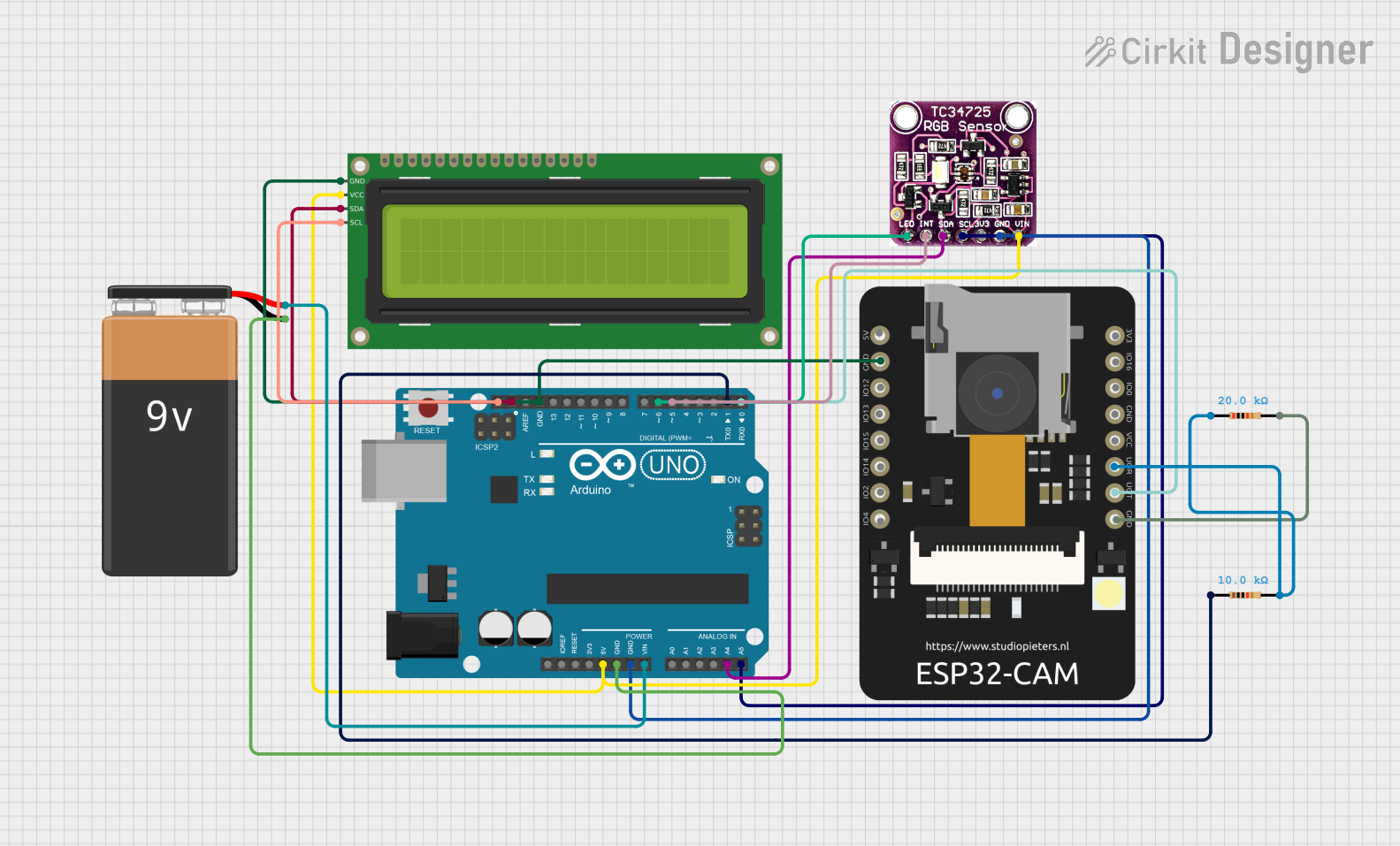 Open Project in Cirkit Designer
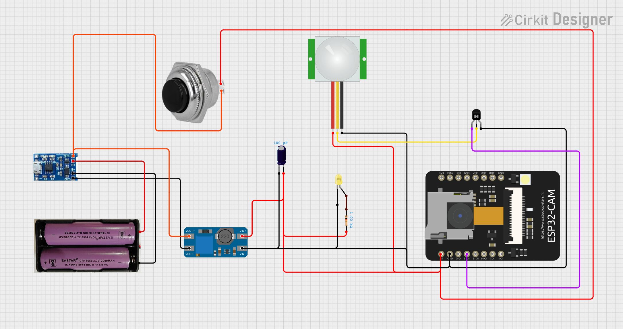 Open Project in Cirkit Designer
 Open Project in Cirkit Designer
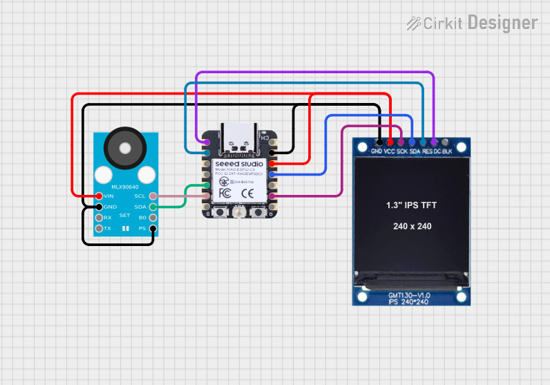 Open Project in Cirkit Designer
Explore Projects Built with 640x480 CMOS Color Camera
Open Project in Cirkit DesignerOpen Project in Cirkit DesignerOpen Project in Cirkit DesignerOpen Project in Cirkit DesignerCommon Applications and Use Cases
- Surveillance and security systems
- Robotics and automation (e.g., object detection, navigation)
- Embedded systems and IoT devices
- Machine vision and image processing
- Educational projects and prototyping with microcontrollers (e.g., Arduino, Raspberry Pi)
Technical Specifications
Below are the key technical details of the 640x480 CMOS Color Camera:
| Parameter | Specification |
|---|---|
| Resolution | 640x480 pixels (VGA) |
| Sensor Type | CMOS |
| Pixel Size | 5.6 µm x 5.6 µm |
| Frame Rate | Up to 30 frames per second (fps) |
| Supply Voltage | 3.3V to 5V |
| Power Consumption | Low power (typically < 150 mW) |
| Interface | Parallel or Serial (e.g., I2C, SPI) |
| Lens Type | Fixed-focus lens |
| Operating Temperature | -20°C to 70°C |
| Dimensions | Compact (e.g., 25mm x 25mm) |
Pin Configuration and Descriptions
The camera module typically comes with a 10-pin or 12-pin interface. Below is an example of a common pinout configuration:
| Pin | Name | Description |
|---|---|---|
| 1 | VCC | Power supply input (3.3V to 5V) |
| 2 | GND | Ground connection |
| 3 | SCL | Serial Clock Line for I2C communication |
| 4 | SDA | Serial Data Line for I2C communication |
| 5 | VSYNC | Vertical synchronization signal |
| 6 | HREF | Horizontal reference signal |
| 7 | PCLK | Pixel clock output |
| 8 | D0-D7 | Data pins (8-bit parallel data output) |
| 9 | RESET | Reset pin (active low) |
| 10 | XCLK | External clock input (used to drive the camera sensor) |
Note: Pin configurations may vary depending on the specific camera module. Always refer to the datasheet of your camera for exact details.
Usage Instructions
How to Use the Component in a Circuit
- Power Supply: Connect the VCC pin to a 3.3V or 5V power source and the GND pin to ground.
- Clock Signal: Provide an external clock signal (XCLK) to the camera module. This can be generated using a microcontroller or an oscillator.
- Data Interface: Use the parallel data pins (D0-D7) or a serial interface (I2C/SPI) to communicate with the camera.
- Synchronization Signals: Connect the VSYNC, HREF, and PCLK pins to the microcontroller to synchronize image data.
- Reset: Use the RESET pin to initialize the camera module during startup.
Important Considerations and Best Practices
- Clock Frequency: Ensure the external clock frequency matches the camera's requirements (e.g., 24 MHz for some modules).
- Voltage Levels: Use level shifters if your microcontroller operates at a different voltage level than the camera.
- Lens Adjustment: If the camera has a manual focus lens, adjust it to achieve the desired focus for your application.
- Noise Reduction: Use decoupling capacitors near the power pins to reduce noise and improve stability.
- Data Processing: The camera outputs raw image data, which may require additional processing (e.g., color conversion, compression).
Example: Connecting to an Arduino UNO
Below is an example of how to connect the 640x480 CMOS Color Camera to an Arduino UNO using the I2C interface:
Wiring Diagram
| Camera Pin | Arduino Pin |
|---|---|
| VCC | 5V |
| GND | GND |
| SCL | A5 (SCL) |
| SDA | A4 (SDA) |
| RESET | Digital Pin 7 |
| XCLK | Digital Pin 9 |
Sample Code
#include <Wire.h> // Include the Wire library for I2C communication

#define CAMERA_RESET_PIN 7 // Define the reset pin for the camera
#define CAMERA_XCLK_PIN 9  // Define the external clock pin for the camera

void setup() {
  pinMode(CAMERA_RESET_PIN, OUTPUT); // Set the reset pin as an output
  pinMode(CAMERA_XCLK_PIN, OUTPUT);  // Set the clock pin as an output

  // Initialize I2C communication
  Wire.begin();

  // Reset the camera
  digitalWrite(CAMERA_RESET_PIN, LOW); // Pull the reset pin low
  delay(10);                           // Wait for 10ms
  digitalWrite(CAMERA_RESET_PIN, HIGH); // Release the reset pin

  // Generate a clock signal on the XCLK pin
  analogWrite(CAMERA_XCLK_PIN, 128); // Use PWM to generate a clock signal

  // Configure the camera (example: setting resolution)
  Wire.beginTransmission(0x42); // Start communication with the camera (address 0x42)
  Wire.write(0x12);             // Write to the resolution register
  Wire.write(0x40);             // Set resolution to 640x480
  Wire.endTransmission();
}

void loop() {
  // Add code to capture and process image data
  // For example, read data from the camera and send it to a display or SD card
}
Note: The camera's I2C address and register settings may vary. Refer to the camera's datasheet for specific configuration details.
Troubleshooting and FAQs
Common Issues and Solutions
No Image Output:
- Ensure the camera is receiving the correct power supply voltage.
- Verify that the external clock signal (XCLK) is being provided.
- Check the I2C/SPI communication lines for proper connections.
Distorted or Noisy Images:
- Adjust the lens focus if the image appears blurry.
- Use decoupling capacitors to reduce power supply noise.
- Ensure proper grounding to minimize interference.
Microcontroller Not Detecting the Camera:
- Double-check the I2C/SPI address and configuration.
- Verify that the RESET pin is properly initialized.
FAQs
Q: Can this camera capture video in low-light conditions?
A: The camera's performance in low-light conditions depends on the sensitivity of the CMOS sensor. For better results, consider using additional lighting.
Q: Is this camera compatible with Raspberry Pi?
A: Yes, the camera can be interfaced with Raspberry Pi using GPIO pins and appropriate libraries (e.g., I2C or SPI).
Q: Can I use this camera for real-time video streaming?
A: Yes, the camera supports real-time video capture at up to 30 fps, but the processing capability of your microcontroller or system will determine the streaming performance.
Q: How do I process the raw image data?
A: Raw image data can be processed using image processing libraries such as OpenCV or custom algorithms on a microcontroller or computer.
By following this documentation, you can effectively integrate and utilize the 640x480 CMOS Color Camera in your projects.