How to Use Adafruit ATSAMD09D14 Breakout: Examples, Pinouts, and Specs
Introduction
The Adafruit ATSAMD09D14 Breakout is a compact, low-power microcontroller board based on the Microchip ATSAMD09D14. It is equipped with an ARM Cortex-M0+ core and a variety of integrated peripherals, making it an excellent choice for projects where space and power consumption are critical. This breakout board is ideal for rapid prototyping and is commonly used in wearable devices, IoT applications, and small-scale automation projects.
Explore Projects Built with Adafruit ATSAMD09D14 Breakout
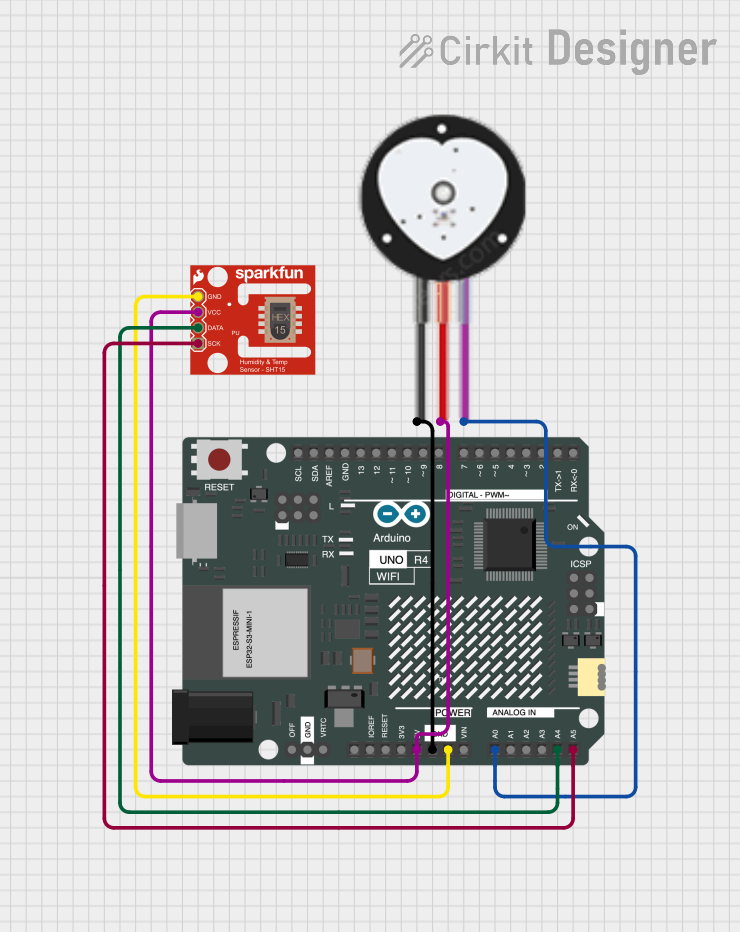
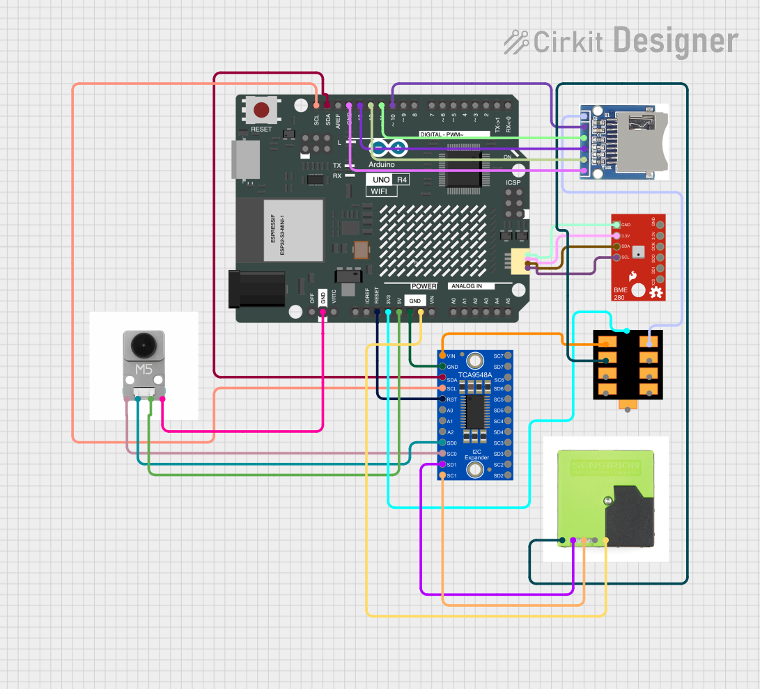


Explore Projects Built with Adafruit ATSAMD09D14 Breakout
Technical Specifications
Key Technical Details
- Microcontroller: ATSAMD09D14
- Core: ARM Cortex-M0+
- Operating Voltage: 3.3V
- Input Voltage: 5V (via USB or VIN)
- Digital I/O Pins: 14
- PWM Channels: 10
- Analog Input Channels: 5 (12-bit ADC)
- Flash Memory: 16 KB
- SRAM: 4 KB
- Clock Speed: 48 MHz
- Interfaces: I2C, SPI, UART
- Dimensions: 25.4mm x 17.8mm
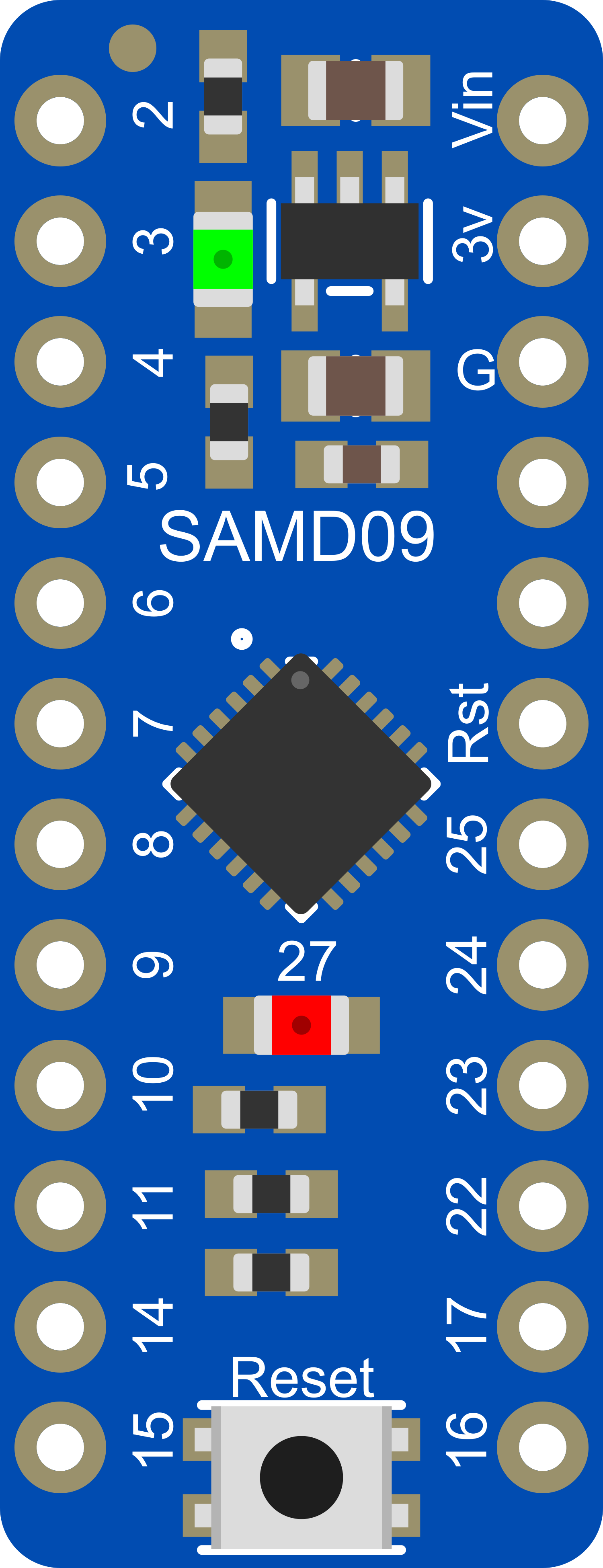
Pin Configuration and Descriptions
| Pin Number | Function | Description |
|---|---|---|
| 1 | VDD | Power supply (3.3V input) |
| 2 | GND | Ground |
| 3-5 | GPIO / ADC | General Purpose I/O, Analog-to-Digital Conv. |
| 6-8 | PWM | Pulse Width Modulation Output |
| 9 | RESET | Reset Input |
| 10 | UART TX | UART Transmit |
| 11 | UART RX | UART Receive |
| 12-14 | SPI (MISO, MOSI, SCK) | SPI Communication Lines |
Usage Instructions
Integrating with a Circuit
- Powering the Board: Connect a 3.3V power supply to the VDD pin and ground to the GND pin.
- Programming: Use the onboard SWD (Serial Wire Debug) interface for programming the ATSAMD09D14.
- I/O Connections: Connect your peripherals to the GPIO pins. Ensure that the voltage levels match the board's operating voltage to prevent damage.
- Communication: Utilize the UART, SPI, or I2C interfaces for communication with other devices or sensors.
Best Practices
- Always verify power supply voltages before connecting to the board to avoid damage.
- Use pull-up or pull-down resistors with GPIO pins when necessary to ensure defined logic levels.
- When using PWM outputs, ensure that the connected devices can handle the frequency and duty cycle.
- For analog readings, ensure that the input voltage does not exceed the maximum ADC input voltage.
Example Code for Arduino UNO
// Example code for interfacing Adafruit ATSAMD09D14 Breakout with Arduino UNO
#include <Wire.h>

void setup() {
  // Initialize serial communication at 9600 baud rate
  Serial.begin(9600);

  // Initialize I2C communication
  Wire.begin();

  // Setup code for ATSAMD09D14 Breakout goes here
}

void loop() {
  // Main code for interacting with the breakout board

  // Example: Read from an I2C sensor connected to the ATSAMD09D14
  Wire.requestFrom(0x48, 1); // Request 1 byte from device address 0x48

  if (Wire.available()) {
    int reading = Wire.read(); // Read the byte
    Serial.println(reading); // Print the reading to the Serial Monitor
  }

  // Add delay between reads
  delay(1000);
}
Troubleshooting and FAQs
Common Issues
- Board Not Powering On: Ensure that the power supply is connected correctly and is within the specified voltage range.
- No Communication: Check the wiring for the communication interfaces (UART, SPI, I2C) and ensure that the correct pins are used.
- Inaccurate ADC Readings: Verify that the input voltage is within the ADC's range and that the reference voltage is stable.
Solutions and Tips
- Use a multimeter to check for proper voltage levels at the power supply and I/O pins.
- Ensure that the board's ground is connected to the ground of other devices in the circuit.
- For I2C communication, ensure that pull-up resistors are connected to the SDA and SCL lines.
FAQs
Q: Can the ATSAMD09D14 Breakout be programmed with the Arduino IDE? A: Yes, with the addition of the appropriate board definitions and configuration, the ATSAMD09D14 can be programmed using the Arduino IDE.
Q: What is the maximum voltage that can be applied to the I/O pins? A: The maximum voltage for the I/O pins is 3.3V. Applying a higher voltage can damage the microcontroller.
Q: Is there onboard voltage regulation? A: No, the board requires a regulated 3.3V input.
Q: How can I reset the ATSAMD09D14 Breakout? A: The board can be reset by pulling the RESET pin low.
For further assistance, consult the Adafruit ATSAMD09D14 Breakout forums or contact Adafruit support directly.