How to Use Arduino 101: Examples, Pinouts, and Specs
Introduction
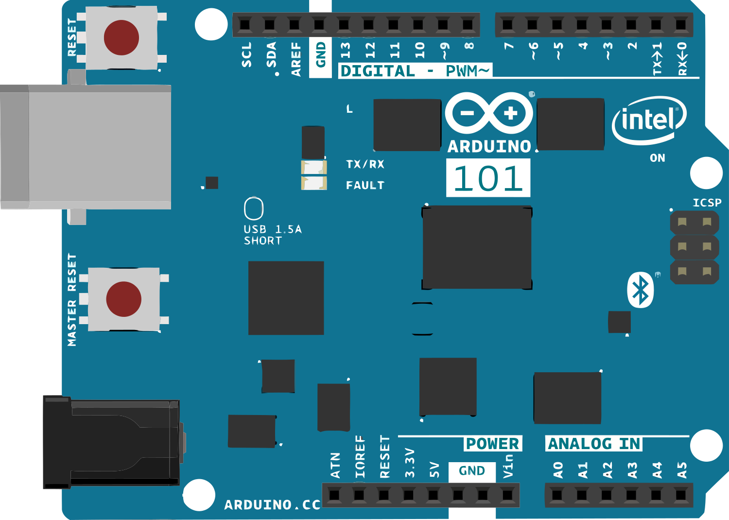
The Arduino 101 is a versatile development board that integrates the Intel Curie module, designed to bring the power of an Intel microcontroller to the Arduino platform. With its built-in Bluetooth Low Energy (BLE) and 6-axis accelerometer/gyroscope, the Arduino 101 is particularly well-suited for Internet of Things (IoT) and wearable technology projects. Its form factor and pin layout are compatible with standard Arduino shields, making it easy to incorporate into existing designs.
Explore Projects Built with Arduino 101

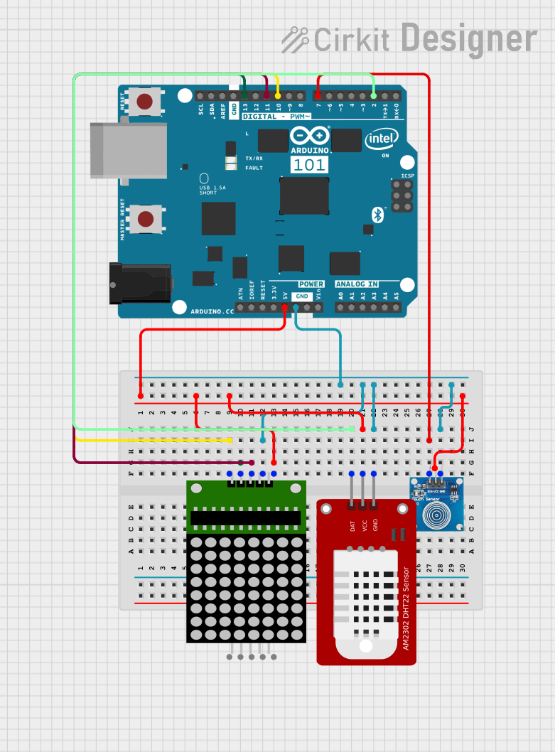
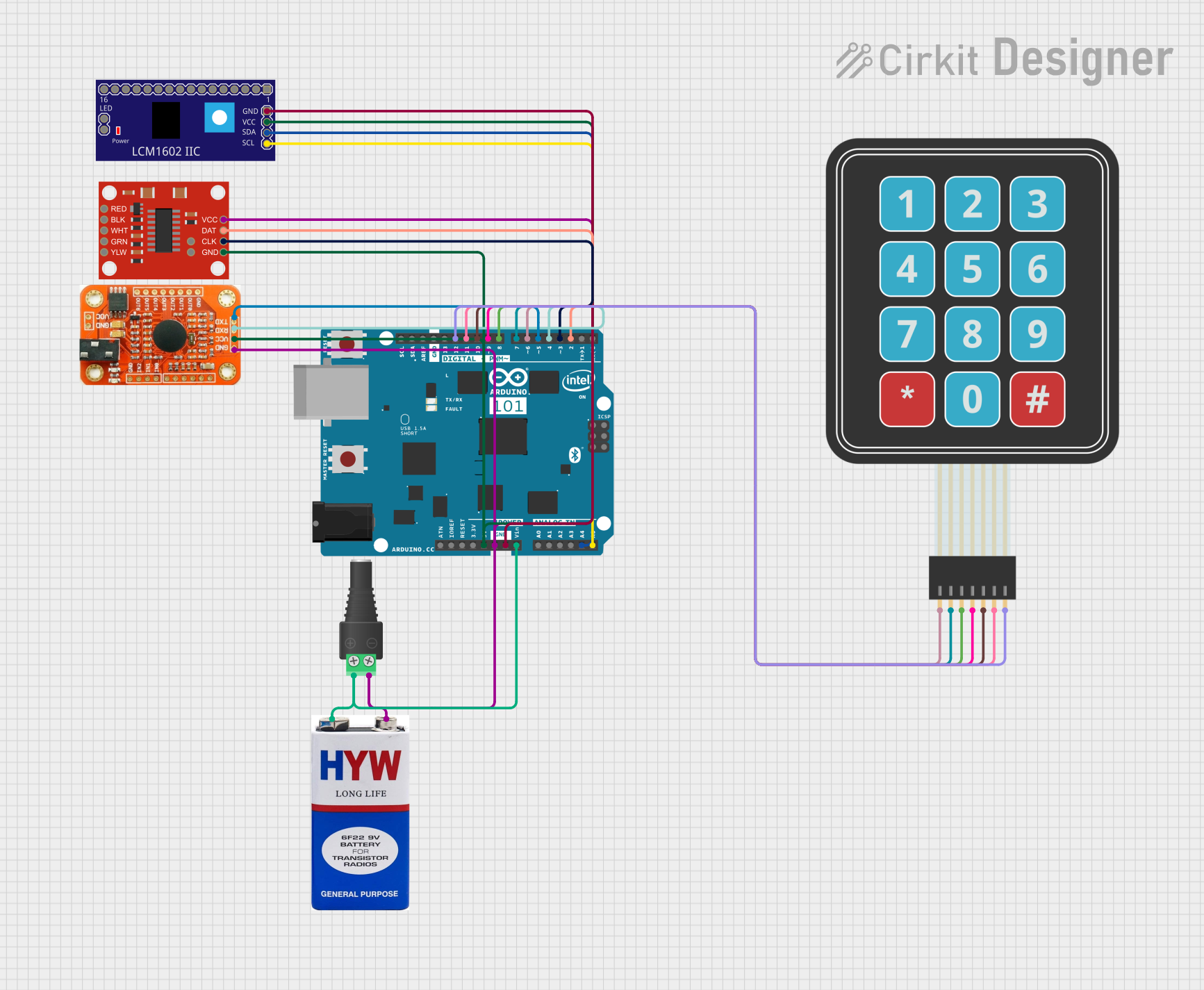
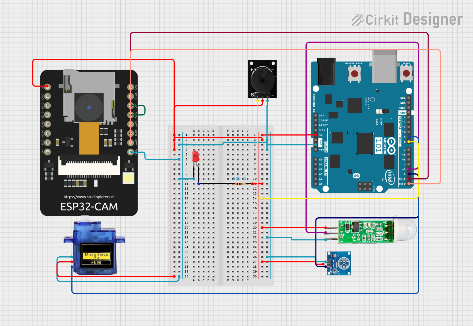
Explore Projects Built with Arduino 101
Common Applications and Use Cases
- Wearable devices
- IoT applications
- Educational projects
- Prototyping for embedded systems
- Motion tracking and detection
Technical Specifications
Key Technical Details
- Microcontroller: Intel Curie
- Operating Voltage: 3.3V
- Input Voltage (recommended): 7-12V
- Input Voltage (limit): 6-20V
- Digital I/O Pins: 14 (of which 4 provide PWM output)
- Analog Input Pins: 6
- DC Current per I/O Pin: 20 mA
- Flash Memory: 196 kB (including 8 kB used by bootloader)
- SRAM: 24 kB
- Clock Speed: 32 MHz
- Bluetooth LE: Built-in
- Sensors: 6-axis accelerometer/gyroscope
Pin Configuration and Descriptions
| Pin Number | Function | Description |
|---|---|---|
| 0 | RX | Serial Receive |
| 1 | TX | Serial Transmit |
| 2-13 | Digital I/O | Digital Input/Output, PWM on 3, 5, 6, and 9 |
| A0-A5 | Analog Input | Analog Input Channels |
| AREF | Analog Ref | Reference voltage for the analog inputs |
| GND | Ground | Ground pin |
| RST | Reset | Resets the microcontroller |
| 3.3V | 3.3V Supply | 3.3V power output (50 mA max) |
| 5V | 5V Supply | Regulated 5V power output (derived from VIN) |
| VIN | Voltage Input | Unregulated input voltage to the board |
Usage Instructions
How to Use the Arduino 101 in a Circuit
Powering the Board:
- Connect a 7-12V power supply to the VIN and GND pins, or plug in the USB cable to provide power.
Connecting I/O Devices:
- Use the digital and analog pins to connect sensors, actuators, and other components. Ensure that the connected devices are compatible with the board's operating voltage of 3.3V.
Programming the Board:
- Connect the Arduino 101 to a computer using a USB cable.
- Use the Arduino IDE to write and upload sketches to the board.
Important Considerations and Best Practices
- Always disconnect the board from power sources before making or altering connections.
- Do not exceed the recommended voltage and current ratings to avoid damaging the board.
- Use a current limiting resistor when connecting LEDs to the digital I/O pins.
- Ensure that the BLE functionality does not interfere with other wireless communications in your project.
Troubleshooting and FAQs
Common Issues
Board not recognized by the computer:
- Check the USB cable and connections.
- Ensure that the correct drivers are installed.
- Try resetting the board using the RST pin.
Sketch not uploading:
- Verify that the correct board and port are selected in the Arduino IDE.
- Check for errors in the code that may prevent compilation.
- Ensure that no other program is using the serial port.
Solutions and Tips for Troubleshooting
- If the board is unresponsive, press the reset button to reboot the microcontroller.
- Check the power supply for proper voltage and current capabilities.
- Consult the Arduino 101 forums and community for help with specific issues.
Example Code for Arduino UNO
// Blink LED example for Arduino 101
void setup() {
  pinMode(13, OUTPUT); // Initialize digital pin 13 as an output.
}

void loop() {
  digitalWrite(13, HIGH); // Turn the LED on (HIGH is the voltage level)
  delay(1000);            // Wait for a second
  digitalWrite(13, LOW);  // Turn the LED off by making the voltage LOW
  delay(1000);            // Wait for a second
}
Note: The above code is a simple blink example that is compatible with the Arduino 101, as it shares the same pin layout for the built-in LED with the Arduino UNO.
Remember to wrap code comments as needed to limit line length to 80 characters, ensuring readability and maintainability of the code.