How to Use Arduino MKR NB 1500: Examples, Pinouts, and Specs
Introduction
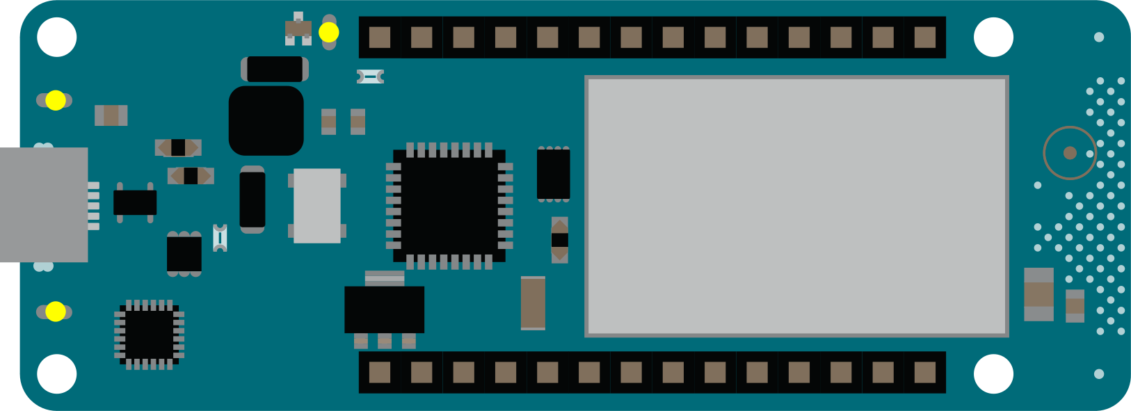
The Arduino MKR NB 1500 is a compact microcontroller board specifically designed for IoT (Internet of Things) applications. It features a low-power ARM Cortex-M0+ processor and integrated NB-IoT (Narrowband IoT) connectivity, making it ideal for low-power, wide-area network (LPWAN) applications. The board also includes a variety of interfaces and sensors, enabling rapid prototyping and deployment of IoT solutions.
Explore Projects Built with Arduino MKR NB 1500
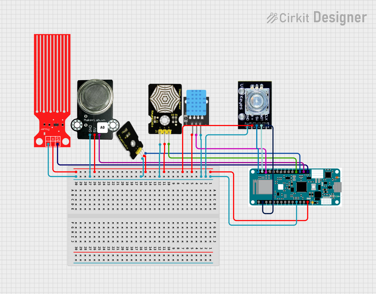

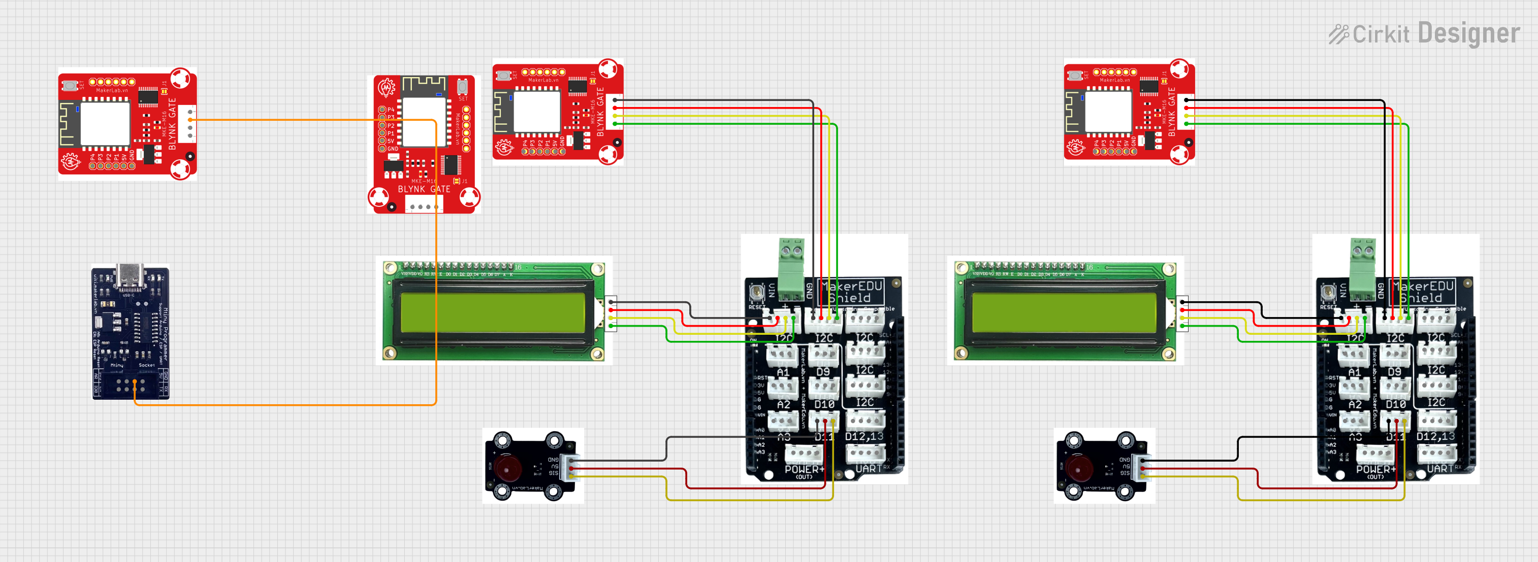
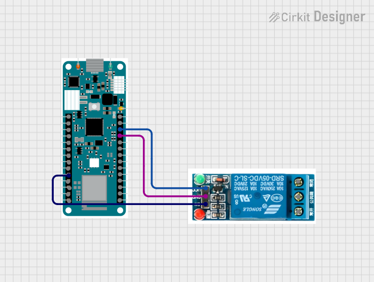
Explore Projects Built with Arduino MKR NB 1500
Common Applications and Use Cases
- Remote environmental monitoring
- Smart agriculture and precision farming
- Asset tracking and logistics
- Industrial IoT (IIoT) applications
- Smart cities and infrastructure monitoring
- Wearable and portable IoT devices
Technical Specifications
Key Technical Details
| Specification | Value |
|---|---|
| Microcontroller | SAMD21 Cortex-M0+ 32-bit ARM MCU |
| Operating Voltage | 3.3V |
| Input Voltage (VIN) | 5V to 12V |
| Digital I/O Pins | 8 (of which 4 can be used as PWM outputs) |
| Analog Input Pins | 7 |
| UART | 1 |
| SPI | 1 |
| I2C | 1 |
| Flash Memory | 256 KB |
| SRAM | 32 KB |
| Clock Speed | 32.768 kHz (RTC), 48 MHz (main clock) |
| Connectivity | NB-IoT, LTE Cat M1 |
| Antenna | uFL connector for external antenna |
| Battery Connector | JST connector for Li-Po battery (3.7V) |
| Dimensions | 67.64 mm x 25 mm |
Pin Configuration and Descriptions
| Pin Name | Type | Description |
|---|---|---|
| VIN | Power Input | External power input (5V to 12V) |
| 3.3V | Power Output | Regulated 3.3V output |
| GND | Ground | Ground connection |
| A0-A6 | Analog Input | Analog input pins (12-bit ADC) |
| D0-D7 | Digital I/O | Digital input/output pins |
| TX | UART TX | UART transmit pin |
| RX | UART RX | UART receive pin |
| SDA | I2C Data | I2C data line |
| SCL | I2C Clock | I2C clock line |
| SPI | SPI Bus | SPI communication pins (MISO, MOSI, SCK, SS) |
| RESET | Reset | Resets the board |
| Li-Po | Power Input | JST connector for Li-Po battery (3.7V) |
| uFL | Antenna | Connector for external NB-IoT antenna |
Usage Instructions
How to Use the Component in a Circuit
Powering the Board:
- Connect a 5V to 12V power source to the VIN pin or use a 3.7V Li-Po battery via the JST connector.
- Alternatively, power the board via the micro-USB port.
Connecting the Antenna:
- Attach an external NB-IoT antenna to the uFL connector for proper network connectivity.
Programming the Board:
- Use the Arduino IDE to write and upload code to the board. Select "Arduino MKR NB 1500" as the board type in the IDE.
Interfacing with Sensors and Actuators:
- Use the digital and analog pins to connect sensors and actuators. Ensure the voltage levels are compatible with the 3.3V logic of the board.
NB-IoT Connectivity:
- Insert a compatible SIM card into the onboard SIM slot.
- Use the
MKRGSMlibrary in the Arduino IDE to establish NB-IoT or LTE Cat M1 connections.
Important Considerations and Best Practices
- Voltage Levels: The board operates at 3.3V logic. Avoid connecting 5V signals directly to the pins to prevent damage.
- Battery Usage: When using a Li-Po battery, ensure it is properly charged and connected to the JST connector.
- Antenna Placement: Position the external antenna away from sources of interference for optimal signal strength.
- Power Consumption: Utilize the board's low-power modes for battery-powered applications to extend operational life.
Example Code for NB-IoT Connection
Below is an example of how to connect the Arduino MKR NB 1500 to an NB-IoT network and send data to a server:
#include <MKRGSM.h>

// Replace with your network credentials
const char PINNUMBER[] = "1234"; // SIM card PIN (if required)
const char GPRS_APN[] = "your_apn"; // APN for your network provider
const char GPRS_LOGIN[] = ""; // Leave blank if not required
const char GPRS_PASSWORD[] = ""; // Leave blank if not required

// Initialize GSM and GPRS objects
GSMClient client;
GPRS gprs;
GSM gsmAccess;

void setup() {
  // Start serial communication for debugging
  Serial.begin(9600);
  while (!Serial);

  Serial.println("Starting Arduino MKR NB 1500...");

  // Connect to the GSM network
  if (gsmAccess.begin(PINNUMBER) != GSM_READY) {
    Serial.println("Failed to connect to GSM network");
    while (true);
  }
  Serial.println("Connected to GSM network");

  // Connect to GPRS
  if (gprs.attachGPRS(GPRS_APN, GPRS_LOGIN, GPRS_PASSWORD) != GPRS_READY) {
    Serial.println("Failed to connect to GPRS");
    while (true);
  }
  Serial.println("Connected to GPRS");
}

void loop() {
  // Connect to a server
  if (client.connect("example.com", 80)) {
    Serial.println("Connected to server");

    // Send HTTP GET request
    client.println("GET / HTTP/1.1");
    client.println("Host: example.com");
    client.println("Connection: close");
    client.println();

    // Wait for server response
    while (client.available()) {
      char c = client.read();
      Serial.print(c);
    }

    client.stop();
  } else {
    Serial.println("Failed to connect to server");
  }

  delay(10000); // Wait 10 seconds before retrying
}
Troubleshooting and FAQs
Common Issues and Solutions
Board Not Detected by Arduino IDE:
- Ensure the correct board type ("Arduino MKR NB 1500") is selected in the IDE.
- Check the USB cable and port connection. Use a data-capable USB cable.
No NB-IoT Connectivity:
- Verify the SIM card is inserted correctly and has an active data plan.
- Check the APN settings in your code and ensure they match your network provider's requirements.
- Ensure the external antenna is securely connected to the uFL connector.
Power Issues:
- If the board does not power on, check the input voltage and ensure it is within the specified range (5V to 12V for VIN or 3.7V for Li-Po).
Overheating:
- Avoid prolonged operation at high current loads. Ensure proper ventilation.
FAQs
Q: Can I use the Arduino MKR NB 1500 with 5V sensors?
A: No, the board operates at 3.3V logic. Use a level shifter to interface with 5V sensors.
Q: What is the maximum range of NB-IoT connectivity?
A: The range depends on the network provider and environmental conditions. Typically, NB-IoT can achieve ranges of several kilometers in urban areas and up to 10-15 km in rural areas.
Q: Can I power the board using only a Li-Po battery?
A: Yes, the board can be powered using a 3.7V Li-Po battery connected to the JST connector. Ensure the battery is charged.
Q: How do I update the firmware on the NB-IoT module?
A: Firmware updates can be performed using the Arduino IDE or a dedicated firmware update tool provided by Arduino. Refer to the official documentation for detailed instructions.