How to Use 12 0 12 transformer: Examples, Pinouts, and Specs
12-0-12 Transformer Documentation
1. Introduction
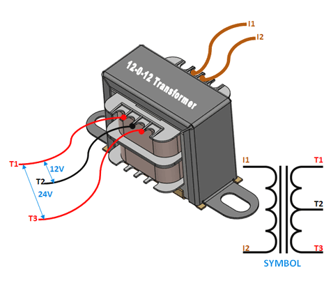
The 12-0-12 transformer is a step-down transformer with a primary winding and two secondary windings. It provides a center-tapped output of 12V, enabling the generation of both positive and negative voltage outputs. This makes it ideal for applications requiring dual power supplies, such as audio amplifiers, operational amplifiers, and other analog circuits.
Common Applications:
- Power supplies for audio amplifiers
- Dual-voltage power supplies for operational amplifiers
- Rectifier circuits for DC voltage generation
- Low-voltage AC power applications
- Educational and prototyping purposes
The 12-0-12 transformer is a versatile and widely used component in electronics, particularly in circuits requiring symmetrical voltage outputs.
2. Technical Specifications
The following table outlines the key technical specifications of the 12-0-12 transformer:
| Parameter | Specification |
|---|---|
| Input Voltage (Primary) | 220V AC (typical) |
| Output Voltage (Secondary) | 12V-0-12V AC (center-tapped) |
| Frequency | 50Hz / 60Hz |
| Power Rating | 12VA to 100VA (varies by model) |
| Current Rating | 1A to 8A (varies by model) |
| Winding Configuration | Primary: Single winding |
| Secondary: Center-tapped (dual 12V) | |
| Insulation Class | Class B or Class F |
| Efficiency | 85% to 95% (typical) |
Pin Configuration and Description
| Pin Number | Label | Description |
|---|---|---|
| 1 | Primary (P1) | Connects to the live (L) terminal of the AC mains. |
| 2 | Primary (P2) | Connects to the neutral (N) terminal of the AC mains. |
| 3 | Secondary (S1) | First secondary winding output (12V AC). |
| 4 | Secondary (S2) | Center-tap (0V reference). |
| 5 | Secondary (S3) | Second secondary winding output (-12V AC). |
3. Usage Instructions
Connecting the Transformer in a Circuit
Primary Side Connection:
- Connect the primary winding pins (P1 and P2) to the AC mains supply (e.g., 220V AC).
- Ensure proper insulation and safety precautions when working with high-voltage AC.
Secondary Side Connection:
- Use the secondary winding pins (S1, S2, and S3) to obtain the desired output.
- For a dual-voltage output:
- S1 provides +12V AC.
- S3 provides -12V AC.
- S2 serves as the center-tap (0V reference).
- For a single 24V AC output, connect S1 and S3, leaving S2 unconnected.
Rectification and Filtering:
- To convert the AC output to DC, use a bridge rectifier circuit followed by a capacitor filter.
- For dual-voltage DC output, connect the center-tap (S2) to the ground of the rectifier circuit.
Important Considerations:
- Power Rating: Ensure the transformer’s power rating matches the load requirements.
- Fusing: Use a fuse on the primary side to protect against overcurrent.
- Heat Dissipation: Transformers can heat up during operation. Ensure proper ventilation or heat sinking if necessary.
- Safety: Always handle the primary side with care, as it is connected to high-voltage AC.
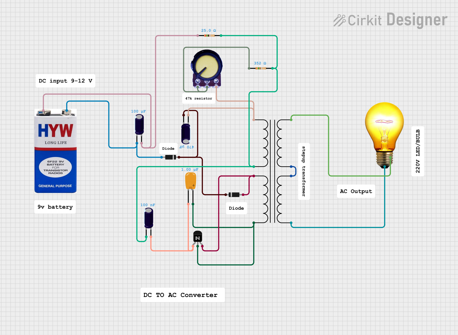
4. Example Circuit: Dual-Voltage Power Supply
Below is an example of how to use the 12-0-12 transformer to create a dual-voltage DC power supply.
Circuit Diagram:
AC Mains (220V) --> Transformer (12-0-12) --> Bridge Rectifier --> Capacitor Filter
Arduino-Compatible Code Example:
If you are using the transformer to power an Arduino UNO via a rectified and regulated DC supply, here is an example code to read analog input values:
// Example Arduino code to read analog input and display the value on the Serial Monitor
// Ensure the transformer output is rectified and regulated to 5V DC before connecting to Arduino.

const int analogPin = A0; // Analog pin connected to the sensor
int sensorValue = 0;      // Variable to store the sensor reading

void setup() {
  Serial.begin(9600); // Initialize serial communication at 9600 baud
}

void loop() {
  sensorValue = analogRead(analogPin); // Read the analog input
  Serial.print("Sensor Value: ");
  Serial.println(sensorValue); // Print the sensor value to the Serial Monitor
  delay(500); // Wait for 500ms before the next reading
}
5. Troubleshooting and FAQs
Common Issues and Solutions:
| Issue | Possible Cause | Solution |
|---|---|---|
| No output voltage on the secondary side | Primary winding not connected properly. | Check the primary connections and AC mains. |
| Transformer overheating | Overloaded or short-circuited secondary. | Reduce the load or check for short circuits. |
| Uneven voltage on secondary windings | Faulty winding or poor connections. | Inspect the transformer for damage. |
| High noise in output voltage | Insufficient filtering in rectifier circuit. | Add larger filter capacitors or use regulators. |
FAQs:
Can I use the 12-0-12 transformer with a 110V AC mains supply?
- No, unless the transformer is specifically rated for 110V input. Check the specifications before use.
What is the maximum current I can draw from the transformer?
- The maximum current depends on the transformer's power rating. For example, a 12VA transformer can supply up to 1A at 12V.
Can I use the transformer to power an Arduino directly?
- No, the transformer outputs AC voltage. You need to rectify and regulate the output to 5V DC before powering the Arduino.
How do I calculate the required fuse rating for the transformer?
- Fuse rating (in amps) = Power rating (in watts) / Input voltage (in volts). Add a safety margin of 10-20%.
6. Safety Precautions
- Always disconnect the transformer from the mains supply before making any connections.
- Use insulated tools and wear protective gear when working with high-voltage circuits.
- Ensure proper grounding of the circuit to avoid electric shocks.
- Do not exceed the transformer's rated power or current to prevent overheating and damage.
This documentation provides a comprehensive guide to understanding, using, and troubleshooting the 12-0-12 transformer. Whether you're a beginner or an experienced user, following these guidelines will help you safely and effectively integrate this component into your projects.
Explore Projects Built with 12 0 12 transformer


Explore Projects Built with 12 0 12 transformer