How to Use BN0 O55 (9DoF IMU): Examples, Pinouts, and Specs
Introduction
The BN0 O55 is a high-performance 9 Degrees of Freedom (9DoF) Inertial Measurement Unit (IMU) developed by Adafruit. It integrates a 3-axis accelerometer, a 3-axis gyroscope, and a 3-axis magnetometer into a single compact module. This combination allows the BN0 O55 to provide precise motion tracking and orientation data, making it ideal for applications such as robotics, drones, augmented reality, and mobile devices.
The BN0 O55 is designed for ease of use, featuring I2C and UART communication interfaces for seamless integration with microcontrollers and development boards like the Arduino UNO. Its onboard sensor fusion algorithms simplify the process of obtaining accurate orientation data, reducing the computational burden on the host system.
Explore Projects Built with BN0 O55 (9DoF IMU)


Explore Projects Built with BN0 O55 (9DoF IMU)
Technical Specifications
Key Technical Details
- Manufacturer: Adafruit
- Model: BN0 O55
- Degrees of Freedom: 9 (3-axis accelerometer, 3-axis gyroscope, 3-axis magnetometer)
- Communication Interfaces: I2C, UART
- Operating Voltage: 3.3V to 5V
- Current Consumption: ~10 mA (typical)
- Accelerometer Range: ±2g, ±4g, ±8g, ±16g
- Gyroscope Range: ±125°/s, ±250°/s, ±500°/s, ±1000°/s, ±2000°/s
- Magnetometer Range: ±1300 µT
- Operating Temperature: -40°C to +85°C
- Dimensions: 20mm x 20mm x 3mm
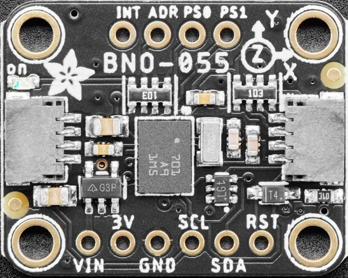
Pin Configuration and Descriptions
The BN0 O55 module has the following pinout:
| Pin | Name | Description |
|---|---|---|
| 1 | VIN | Power input (3.3V to 5V). |
| 2 | GND | Ground connection. |
| 3 | SDA | I2C data line. |
| 4 | SCL | I2C clock line. |
| 5 | TX | UART transmit pin (for serial communication). |
| 6 | RX | UART receive pin (for serial communication). |
| 7 | INT | Interrupt pin (used for event notifications). |
| 8 | RST | Reset pin (active low, used to reset the module). |
Usage Instructions
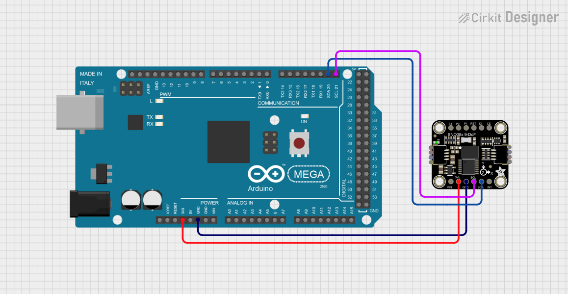
How to Use the BN0 O55 in a Circuit
Powering the Module:
Connect the VIN pin to a 3.3V or 5V power source and the GND pin to the ground of your circuit.Communication Interface:
- For I2C communication, connect the SDA and SCL pins to the corresponding pins on your microcontroller. Use pull-up resistors (typically 4.7kΩ) if not already present on the board.
- For UART communication, connect the TX and RX pins to the RX and TX pins of your microcontroller, respectively.
Interrupts and Reset:
- The INT pin can be connected to a GPIO pin on your microcontroller to handle interrupts.
- The RST pin can be connected to a GPIO pin or left unconnected if not used.
Sensor Fusion:
The BN0 O55 includes onboard sensor fusion algorithms to provide orientation data (e.g., Euler angles or quaternions). Use the Adafruit Unified Sensor library to access this data.
Important Considerations and Best Practices
- Ensure the module is mounted securely to minimize vibrations, which can affect sensor readings.
- Calibrate the accelerometer, gyroscope, and magnetometer for accurate measurements.
- Avoid placing the module near strong magnetic fields or sources of electromagnetic interference.
- Use appropriate level shifters if interfacing with a 5V microcontroller.
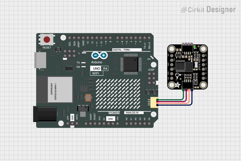
Example Code for Arduino UNO
Below is an example of how to use the BN0 O55 with an Arduino UNO via I2C:
#include <Wire.h>
#include <Adafruit_Sensor.h>
#include <Adafruit_BNO055.h>

// Create an instance of the BNO055 sensor
Adafruit_BNO055 bno = Adafruit_BNO055(55, 0x28); // Default I2C address is 0x28

void setup() {
  Serial.begin(9600); // Initialize serial communication
  while (!Serial) {
    delay(10); // Wait for Serial Monitor to open
  }

  Serial.println("Initializing BNO055...");

  // Initialize the BNO055 sensor
  if (!bno.begin()) {
    Serial.println("Failed to initialize BNO055! Check connections.");
    while (1);
  }

  bno.setExtCrystalUse(true); // Use external crystal for better accuracy
  Serial.println("BNO055 initialized successfully.");
}

void loop() {
  // Get orientation data (Euler angles)
  sensors_event_t event;
  bno.getEvent(&event);

  // Print orientation data to Serial Monitor
  Serial.print("Heading: ");
  Serial.print(event.orientation.x);
  Serial.print("°, Pitch: ");
  Serial.print(event.orientation.y);
  Serial.print("°, Roll: ");
  Serial.print(event.orientation.z);
  Serial.println("°");

  delay(100); // Delay for readability
}
Troubleshooting and FAQs
Common Issues and Solutions
Sensor Not Detected:
- Ensure the I2C address (default: 0x28) matches the one in your code.
- Check the wiring for loose or incorrect connections.
- Verify that pull-up resistors are present on the SDA and SCL lines.
Inaccurate Readings:
- Perform a calibration routine for the accelerometer, gyroscope, and magnetometer.
- Ensure the module is mounted on a stable surface away from vibrations.
- Avoid magnetic interference from nearby components.
Module Not Responding:
- Check the power supply voltage and current requirements.
- Reset the module using the RST pin or by power cycling.
FAQs
Q: Can the BN0 O55 be used with 5V microcontrollers?
A: Yes, the BN0 O55 supports 3.3V to 5V logic levels, making it compatible with 5V microcontrollers like the Arduino UNO.
Q: How do I calibrate the BN0 O55?
A: Use the Adafruit BNO055 library's calibration functions. Follow the instructions in the library documentation to perform a full calibration.
Q: What is the maximum I2C clock speed supported?
A: The BN0 O55 supports I2C clock speeds up to 400 kHz (Fast Mode).
Q: Can I use the BN0 O55 for GPS-based navigation?
A: While the BN0 O55 provides orientation data, it does not include GPS functionality. You can combine it with a GPS module for navigation applications.